Liquefied natural gas station

A technology for liquefied natural gas and gas filling station, which is applied in gas/liquid distribution and storage, equipment for loading into pressure vessels, container filling methods, etc. Reasonable and other issues, to achieve the effect of being conducive to fully automatic control, conducive to automatic control, and reducing natural gas consumption

Active Publication Date: 2012-07-25
沈军
View PDF4 Cites 9 Cited by
  • Summary
  • Abstract
  • Description
  • Claims
  • Application Information

AI Technical Summary

Problems solved by technology

[0002] Existing liquefied natural gas (also known as LNG, this article includes liquid coalbed methane, liquid shale gas, etc.) gas filling stations, there are many pipelines or loops, which absorb more heat, and correspondingly waste a lot of LNG; mainly reflected in the lack of pipeline design Reasonable, it needs to adjust the saturation of the storage tank vaporizer, the process is complicated, and the function of the pump is not well utilized, resulting in many pipelines, difficult repair or maintenance, increased control difficulty, or too much manual intervention, and no fully automatic control

Method used


Image

  • Liquefied natural gas station
  • Liquefied natural gas station
  • Liquefied natural gas station

Examples


Embodiment 1

[0077] Technical solution 1:

[0078] The liquid natural gas filling station is composed of storage tanks, pumps, filling machines, electric control systems, valves and pipelines. Its technical characteristics are:

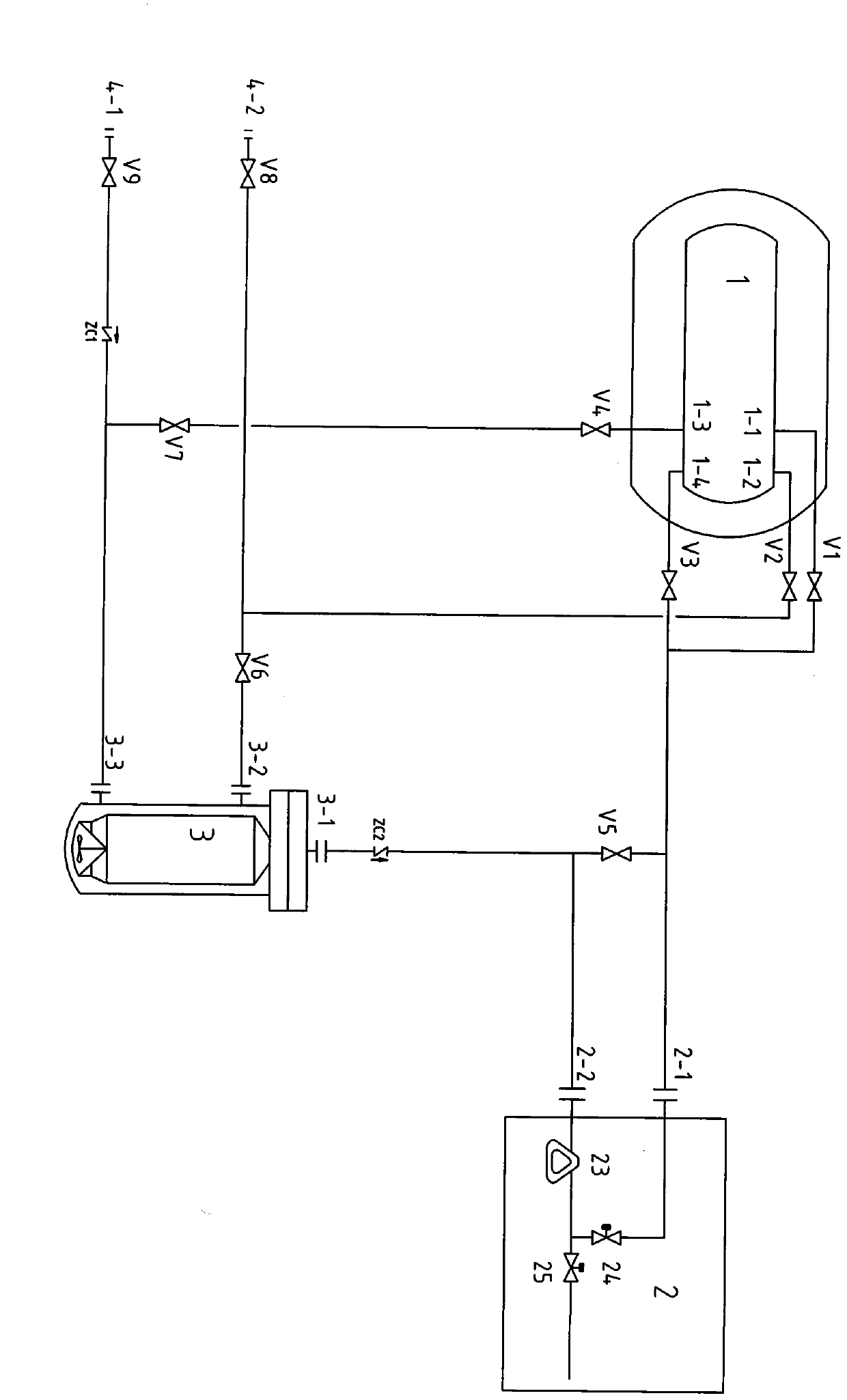
[0079] exist figure 1 Among them, option one:

[0080] (Transportation of LNG tank trucks) The unloading liquid phase port 4-1, the liquid inlet port 3-3 in the pump 3, and the bottom liquid phase liquid outlet port 1-3 in the storage tank 1 are connected through valves and pipelines (the connection form is Inverted "T"-shaped connection); the three form a connected circuit or pipeline, that is, LNG tanker unloading liquid phase port 4-1, valve V9, check valve ZC1, pump liquid inlet 3-3, storage tank 1 The pipeline consisting of the bottom liquid phase liquid outlet 1-3, valve V4, and valve V7;

[0081] (Transportation of LNG tank trucks) unloading gas phase port 4-2, gas return port 3-2 in pump 3, and upper gas phase port 1-2 in storage tank 1 are connected th...

Embodiment 2

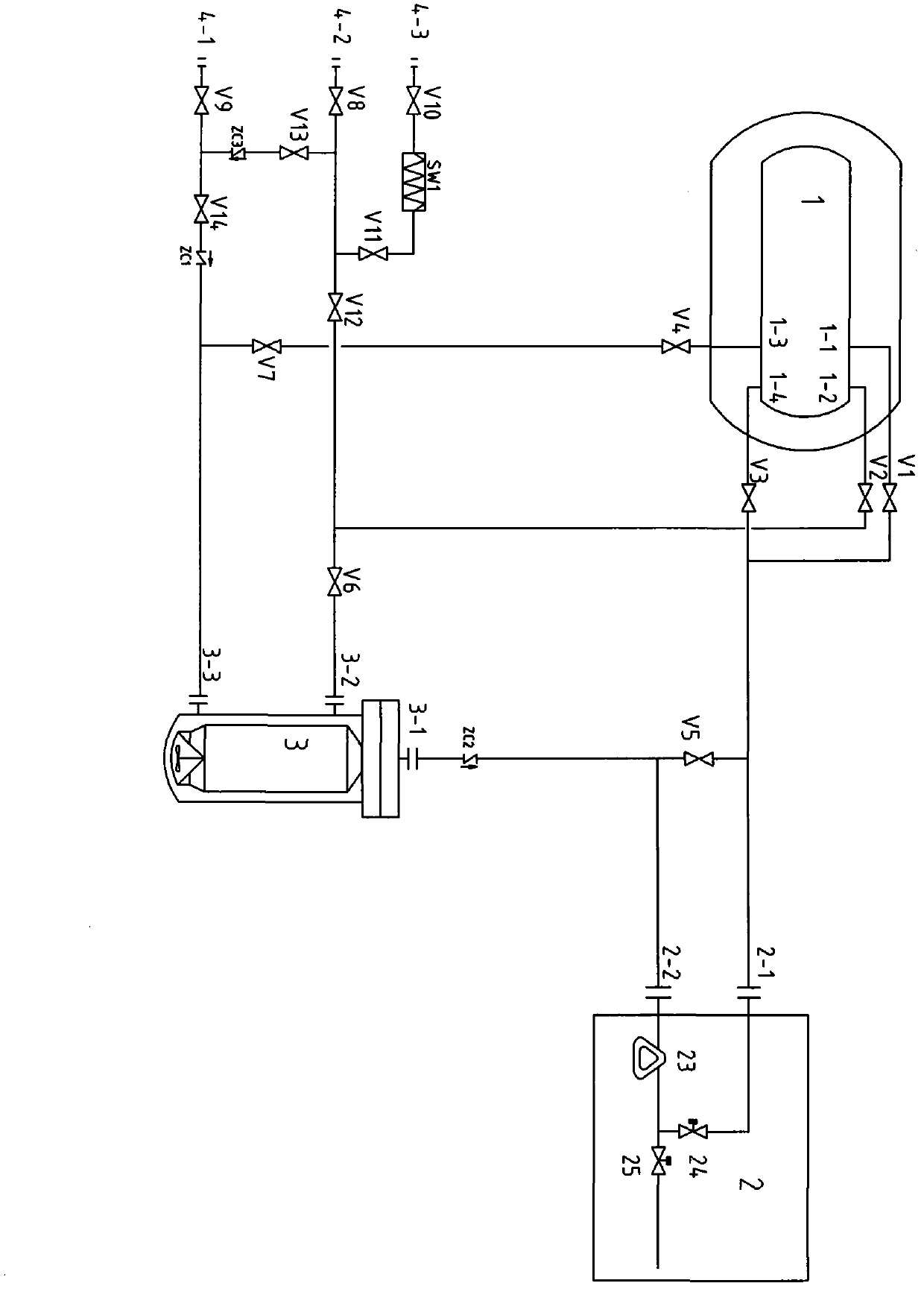
[0099] Add pipelines in Scheme 1 to expand applications, for example:

[0100] exist figure 2 In the middle, add 4-3 liquid phase, increase carburetor SW1, and parallel connection with unloading gas phase 4-2 pipeline, increase self-pressurized unloading function; it can also cooperate with pump unloading to increase the inlet pressure of the pump;

[0101] Between the unloading gas phase 4-2 pipeline and 4-1 liquid phase pipeline, add a valve and a check valve to achieve gas-liquid balance, let the BOG in the storage tank enter the tank car, and make the low temperature in the tank car unsaturated Liquid LNG liquefies BOG to reduce BOG emissions.

[0102] Unloading process steps:

[0103] The first method, air-gas balance self-pressurized unloading:

[0104] Close V6, V13, open V2, V12, V8, and balance the BOG in the storage tank and the BOG in the tank car first, that is, 1 storage tank→1-2→V2→V12→V8→4-2→inside the tank car;

[0105] After balancing, close V12, open V10...

Embodiment 3

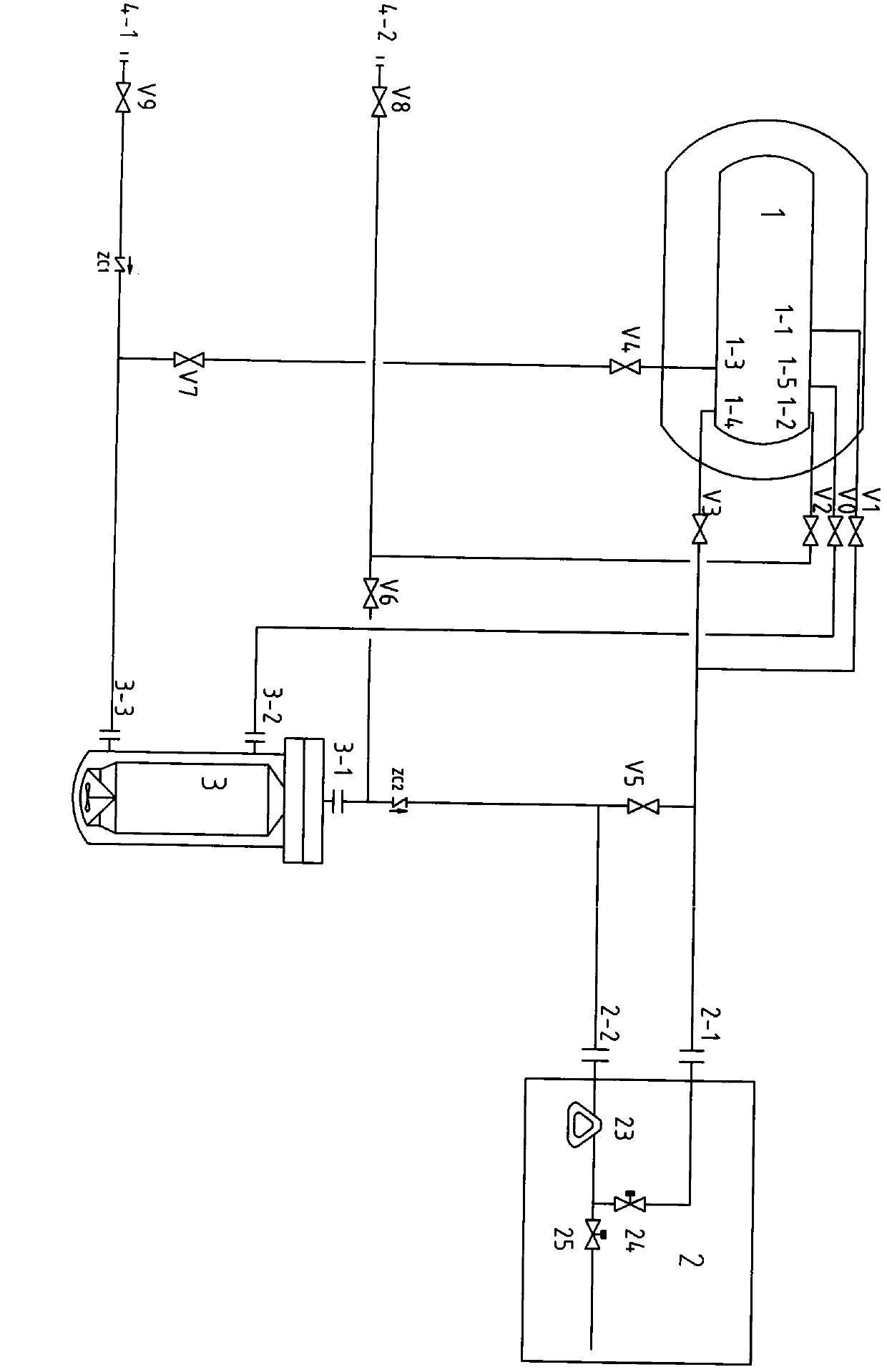
[0117] Technical solution 2:

[0118] The liquid natural gas filling station is composed of storage tanks, pumps, filling machines, electric control systems, valves and pipelines. Its technical characteristics are:

[0119] (Transportation of LNG tanker) Unloading liquid phase port 4-1, liquid inlet port 3-3 in pump 3, bottom liquid phase liquid outlet port 1-3 in storage tank 1 are directly connected by valves and pipelines (connection form Inverted "T"-shaped connection); that is, LNG tank truck unloading liquid phase port 4-1, valve V9, check valve ZC1, pump liquid inlet 3-3, bottom liquid phase liquid outlet 1 in storage tank 1 -3. The pipeline composed of valve V4 and valve V7;

[0120] (Transportation of LNG tanker) unloading gas phase port 4-2, liquid outlet 3-1 in pump 3, and upper gas phase port 1-2 in storage tank 1 are directly connected through valves and pipelines (the connection form is inverted " T" type word connection); that is (LNG tanker) unloading gas pha...


PUM


Abstract

A liquefied natural gas station comprises a storage tank, a pump, a gas dispenser, an electric control system, valves and pipelines, and is characterized in that an unloading liquid-phase opening, a liquid inlet of the pump and a liquid outlet at the bottom of the storage tank are connected by the valves and the pipelines, an unloading gas-phase opening, a gas return opening of the pump and a gas-phase opening on the upper portion of the storage tank are connected by the valves and the pipelines, after a liquid inlet and a liquid return opening of the gas dispenser are connected in parallel by a pipeline and a valve to form a parallel connection circuit, one end of the parallel connection circuit is connected with an upper liquid inlet and a lower liquid inlet of the storage tank in parallel by pipelines, and the other end of the parallel connection circuit is connected with a liquid outlet of the pump by a valve and a pipeline. Alternatively, the unloading liquid-phase opening, the liquid inlet of the pump and the liquid outlet at the bottom of the storage tank are connected by the valves and the pipelines, the unloading gas-phase opening, a liquid outlet of the pump and the gas-phase opening of the upper portion of the storage tank are connected by the valves and the pipelines, the gas-phase opening of the storage tank is directly connected with the gas return opening by a valve and a pipeline, after the liquid inlet and the liquid return opening of the gas dispenser are connected in parallel by pipelines and a valve to form a parallel connection circuit, one end of the parallel connection circuit is connected with the upper liquid inlet and the lower liquid inlet of the storage tank in parallel by pipelines, and the other end of the parallel connection circuit is connected with the liquid outlet of the pump by a valve and a pipeline.

Description

technical field [0001] The invention relates to a liquefied natural gas filling station, which has a unique and simple pipeline connection method. There are only three or four pipelines or loops connected in the whole station, and less heat is absorbed by the pipelines, which reduces the consumption of natural gas and is beneficial The fully automatic control belongs to the energy application field. Background technique [0002] Existing liquefied natural gas (also known as LNG, this article includes liquid coalbed methane, liquid shale gas, etc.) gas filling stations, there are many pipelines or loops, which absorb more heat, and correspondingly waste a lot of LNG; mainly reflected in the lack of pipeline design Reasonable, it needs to adjust the saturation of the storage tank vaporizer, the process is complicated, and the function of the pump is not well utilized, resulting in many pipelines, difficult repair or maintenance, increased control difficulty, or too much manual...

Claims


Application Information

Patent Timeline
Patent Type & Authority Applications(China)
IPC IPC(8): F17D1/04F17D1/14F17C5/02
Inventor 沈军薛向东谢南群
Owner 沈军
Why Eureka
Try Eureka