Optical fiber drawing heating furnace device using H2 and optical fiber drawing method

A heating furnace and wire drawing technology, applied in the field of optical fiber manufacturing, to reduce production costs, improve roundness, and improve the quality of optical fibers

Pending Publication Date: 2019-04-26
TONGDING INTERCONNECTION INFORMATION CO LTD
View PDF9 Cites 0 Cited by
  • Summary
  • Abstract
  • Description
  • Claims
  • Application Information

AI Technical Summary

Problems solved by technology

[0004] h 2 The thermal conductivity is higher than that of He and has better thermal conductivity. Use H 2 Replacing He is more conducive to keeping the temperature field in the furnace stable, but H 2 It is a flammable and explosive gas, and the drawing heating furnace is a high-temperature environment, so it is very dangerous when used

Method used


Image

  • Optical fiber drawing heating furnace device using H2 and optical fiber drawing method
  • Optical fiber drawing heating furnace device using H2 and optical fiber drawing method
  • Optical fiber drawing heating furnace device using H2 and optical fiber drawing method

Examples


Embodiment Construction

[0039] It should be noted that, in the case of no conflict, the embodiments of the present invention and the features in the embodiments can be combined with each other.

[0040]In describing the present invention, it should be understood that the terms "center", "longitudinal", "transverse", "upper", "lower", "front", "rear", "left", "right", " The orientations or positional relationships indicated by "vertical", "horizontal", "top", "bottom", "inner" and "outer" are based on the orientations or positional relationships shown in the drawings, and are only for the convenience of describing the present invention and Simplified descriptions, rather than indicating or implying that the device or element referred to must have a particular orientation, be constructed and operate in a particular orientation, and thus should not be construed as limiting the invention. In addition, the terms "first", "second", etc. are used for descriptive purposes only, and should not be understood a...


PUM

PropertyMeasurementUnit
diameteraaaaaaaaaa

Abstract

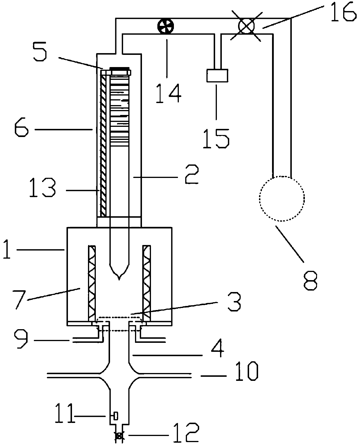
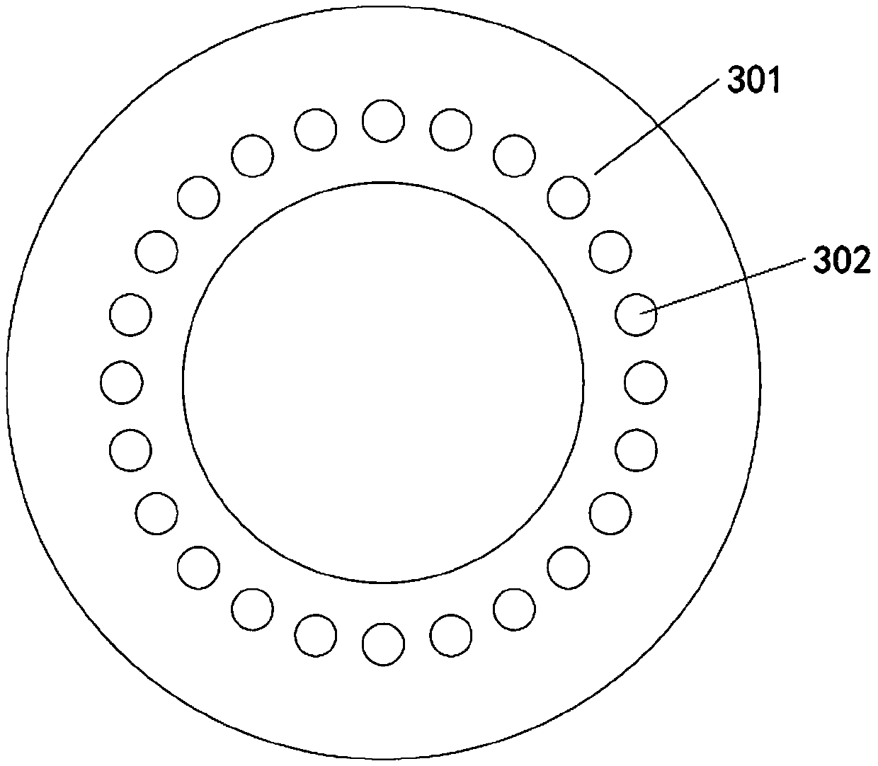
The invention provides an optical fiber drawing heating furnace device using H2 and an optical fiber drawing method. The optical fiber drawing heating furnace device using H2 comprises a furnace body,wherein a sealing cylinder communicated mutually is mounted at the top of the furnace body, an optical fiber preform fixing and moving unit is mounted in the sealing cylinder; a gas recovery unit iscommunicated at the top of the sealing cylinder; a heating coil for heating an optical fiber preform is mounted in the furnace body; a gas distribution unit and an annealing tube are mounted at the bottom of the furnace body, the gas distribution unit is communicated with a hydrogen inlet pipeline, and the annealing pipe is communicated with an argon inlet pipeline; the hydrogen inlet pipeline isarranged above the argon inlet pipeline. The upper part of the optical fiber drawing heating furnace device using H2 is integrally sealed and the lower part of the optical fiber drawing heating furnace device using H2 uses inert gas, namely argon to isolate air, so that hydrogen can be used safely, and the price of the hydrogen is lower than that of helium. Therefore, the production cost of optical fibers can be reduced.

Description

technical field [0001] The invention belongs to the field of optical fiber manufacturing, in particular to a method using H 2 An optical fiber drawing heating furnace device and method. Background technique [0002] As an extremely important functional device in optical fiber drawing, the drawing heating furnace can heat the preform, melt the optical fiber preform in the drawing heating furnace, and form an optical fiber with a diameter within the range of 125±1μm under certain drawing conditions. In order to prevent the preform from being oxidized in a high-temperature environment, it is usually protected by an inert gas (He and Ar). Among them, He has a high thermal conductivity and has the function of maintaining a stable temperature field in the furnace. [0003] He is a global strategic resource, of which the United States is the world's largest producer and supplier of He, followed by Algeria, Qatar, Russia and Poland (the above five countries are known as the Helium ...

Claims


Application Information

Patent Timeline
Patent Type & Authority Applications(China)
IPC IPC(8): C03B37/029
CPCC03B37/029C03B2205/61
Inventor 沈小平李彪杨志杰沈佳满小忠朱坤颜永庆
Owner TONGDING INTERCONNECTION INFORMATION CO LTD
Why Eureka
Try Eureka