Multiphase power supply circuit

一种供电电路、多相电源的技术,应用在数据处理电源、电气元件、测量装置等方向,能够解决数据不准确、影响调节的效果、干扰等问题,达到延长采样时间、提高准确性、增加采样数量的效果

一种供电电路、多相电源的技术,应用在数据处理电源、电气元件、测量装置等方向,能够解决数据不准确、影响调节的效果、干扰等问题,达到延长采样时间、提高准确性、增加采样数量的效果

CN102609066AInactive Publication Date: 2012-07-25HONG FU JIN PRECISION IND (SHENZHEN) CO LTD +1

Image

  • Multiphase power supply circuit
  • Multiphase power supply circuit

Examples


Embodiment Construction

[0029] The present invention will be further described in detail below in conjunction with the accompanying drawings.

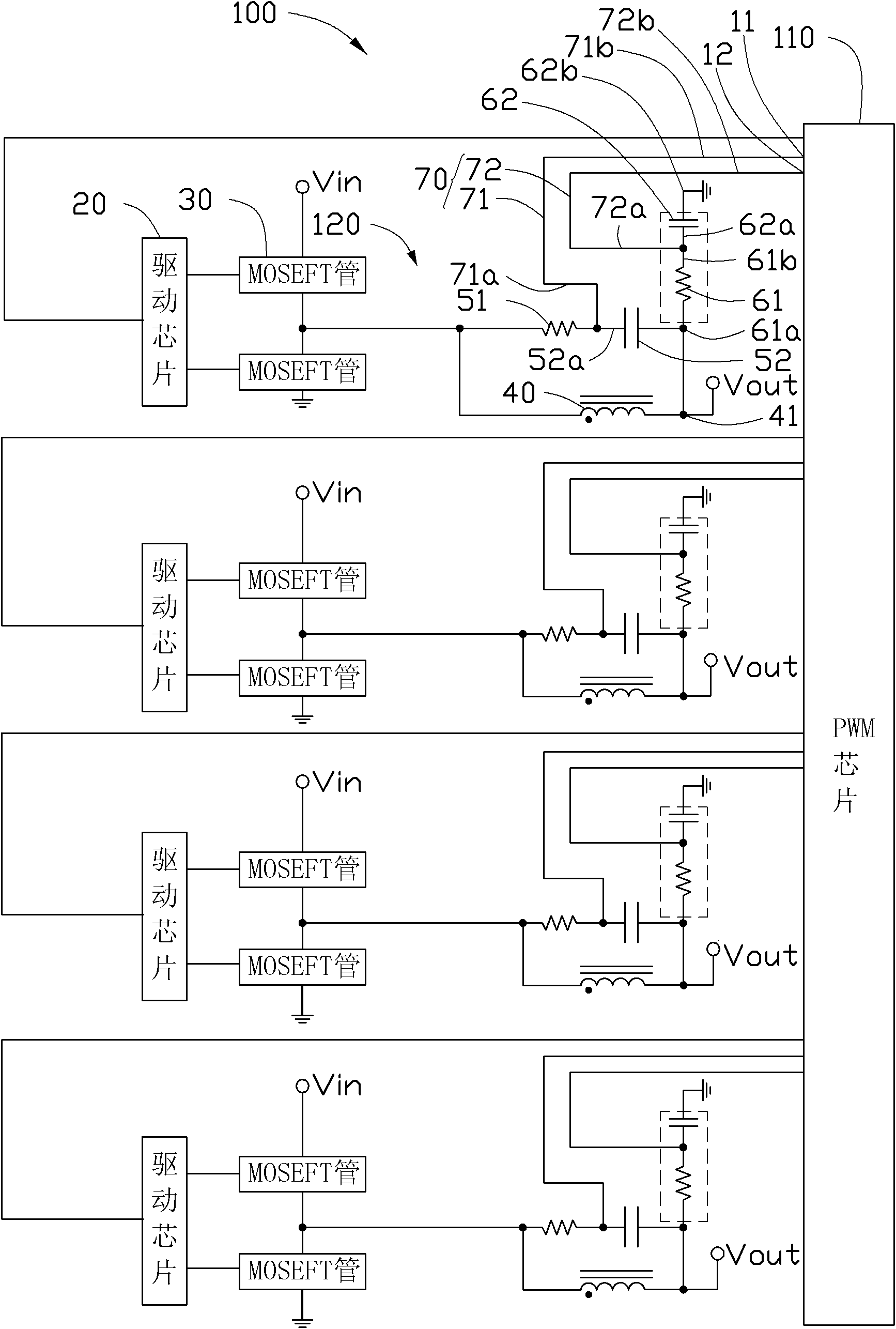
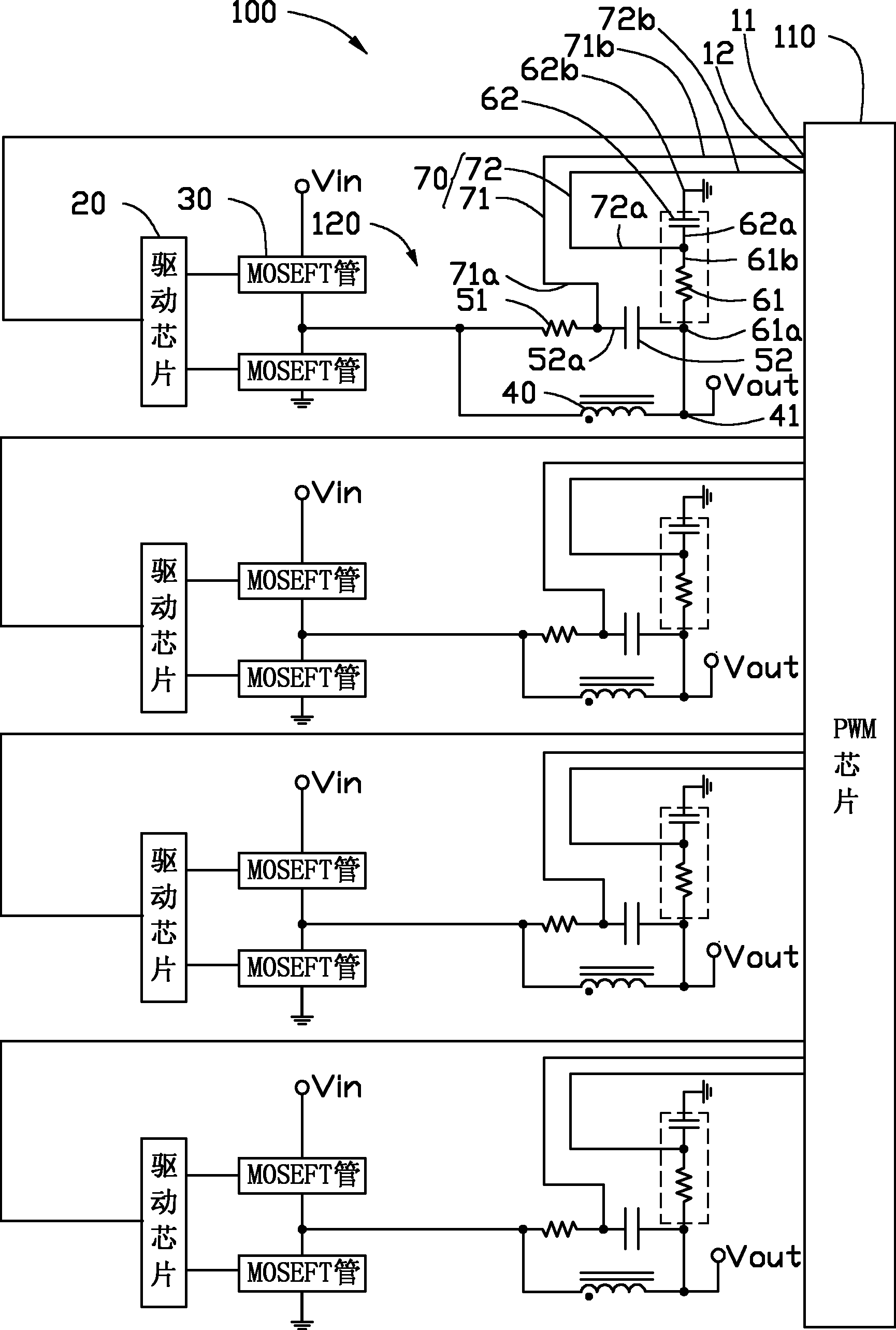
[0030] see figure 1 , the multi-phase power supply circuit 100 provided by the present invention includes a PWM chip (pulse width modulation chip) 110 and a plurality of sub-circuits 120 . In this embodiment, the multi-phase power supply circuit 100 is a four-phase power supply circuit, including four sub-circuits 120 . Each of the sub-circuits 120 includes a driver chip 20, a group of MOSFETs (power field effect transistors) 30, an inductor 40, a first resistor 51, a first capacitor 52, a second resistor 61, a second Capacitor 62 and a differential line pair 70 .

[0031] The PWM chip 110 is electrically connected to each of the driving chips 20 for outputting four-phase control signals to the four driving chips 20 respectively. The driving chips 20 are respectively electrically connected to the groups of MOSEFT transistors 30 for driving the groups of MO...


PUM


Abstract

A multiphase power supply circuit comprises a PWM (pulse-width modulation) chip and a plurality of sub-circuits. Each sub-circuit comprises an inductor, a first resistor, a first capacitor, a differential line pair, a second resistor and a second capacitor. The first resistor and the first capacitor in each sub-circuit are serially connected, and then are parallelly connected with the inductor in the sub-circuit. The differential line pair in each sub-circuit comprises a first differential line and a second differential line. The first differential line in each sub-circuit is connected between a joint of the corresponding first resistor and the corresponding first capacitor and a terminal of a current sensor of the PWM chip. One end of the second resistor in each sub-circuit is electrically connected to a joint of the corresponding capacitor and the corresponding inductor, one end of the second resistor in each sub-circuit is serially connected with the corresponding second capacitor while the other end of the second capacitor is ground, the second differential line in each sub-circuit is electrically connected between a joint of the corresponding second resistor and the corresponding second capacitor and another terminal of a current sensor of the PWM chip, and the ratio of capacitances of the second capacitors of the sub-circuits is equal to that of lengths of the corresponding differential line pairs. The circuit can prolong sampling time of the long differential line pairs, and increases sampling accuracy.

Description

technical field [0001] The invention relates to a multi-phase power supply circuit. Background technique [0002] In the existing CPU multi-phase power supply circuit, the PWM chip outputs multi-phase control signals to multiple driver chips, and each driver chip drives a group of MOSEFT tubes, and the MOSEFT tubes drop the 12V voltage to a suitable value for the CPU through an inductor. voltage to power the CPU. The PWM chip samples the voltage of the inductor in each phase in a time period, divides the sampled voltage by the proportional coefficient to obtain the current of each phase, then adds the current of each phase, and divides it by the number of phases to obtain the average current. The PWM chip adjusts the output pulse width according to the obtained average current to adjust the voltage provided to the CPU. The existing way to obtain the voltage is to connect an identical RC circuit in parallel at both ends of the inductor of each phase, and obtain the voltage...

Claims


Application Information

Patent Timeline
25 Jul 2012
Publication
CN102609066A
IPC
G06F1/26; H02M3/06
CPC
H02M3/1584; G06F1/26
Inventors
童松林; 沈玲玲