Multilayer ceramic electronic component

一种电子部件、陶瓷的技术,应用在外部电极的结构领域,达到姿态稳定的效果

Active Publication Date: 2012-07-25
MURATA MFG CO LTD
View PDF6 Cites 21 Cited by
  • Summary
  • Abstract
  • Description
  • Claims
  • Application Information

AI Technical Summary

Problems solved by technology

That is, if it is a laminated ceramic electronic component with at least two layers of external electrodes, it may encounter the above-mentioned problems

Method used


Image

  • Multilayer ceramic electronic component
  • Multilayer ceramic electronic component
  • Multilayer ceramic electronic component

Examples


no. 1 Embodiment approach

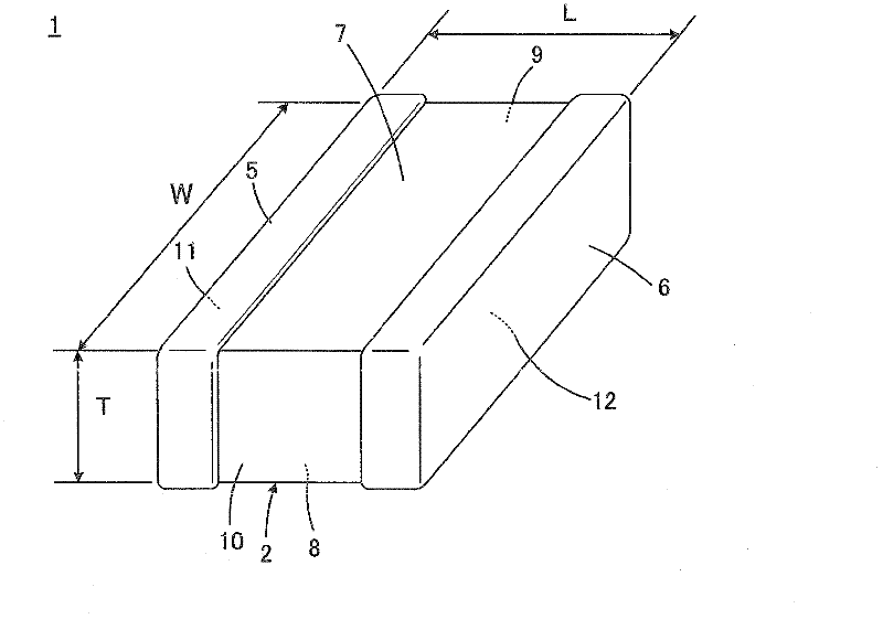
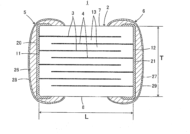
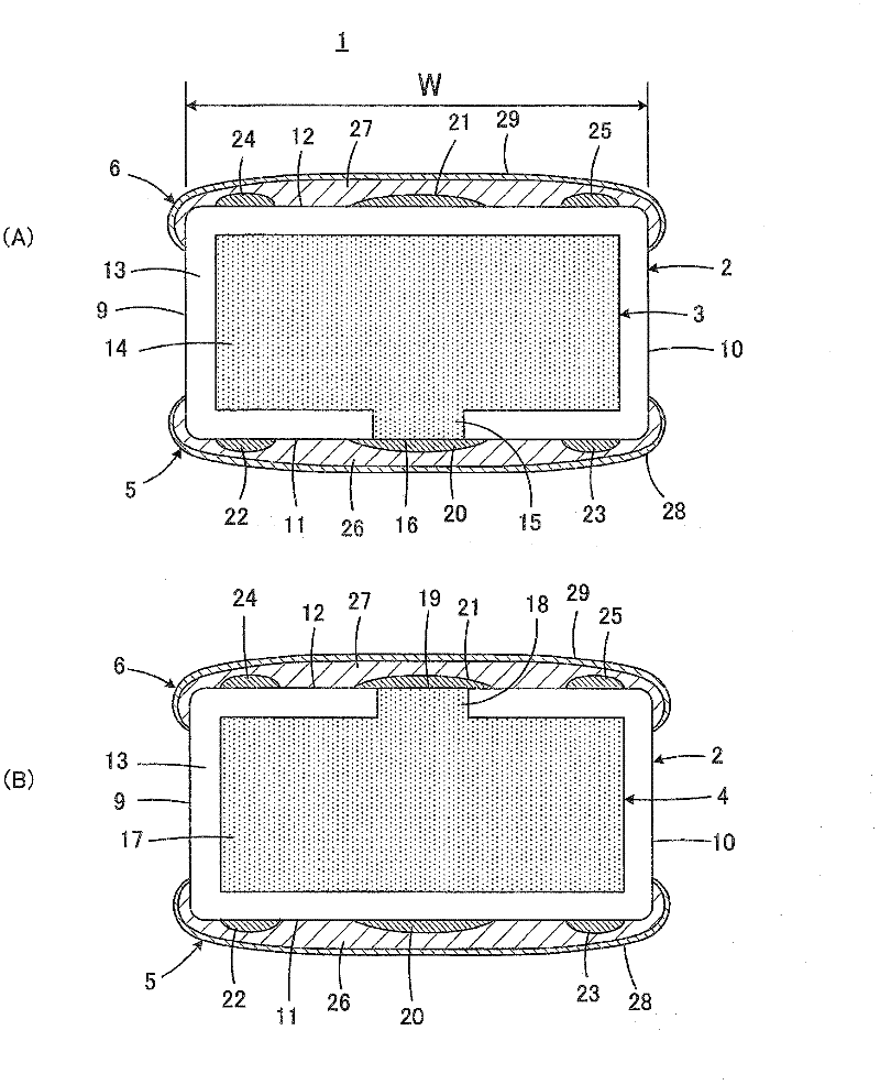
[0067] Figure 1 to Figure 6 It is a figure for demonstrating the 1st Embodiment of this invention. The multilayer ceramic capacitor 1 of the first embodiment is an ESR control type. Multilayer ceramic capacitor 1 includes a ceramic body 2 , internal electrodes 3 and 4 arranged inside ceramic body 2 , and external electrodes 5 and 6 arranged on the outer surface of ceramic body 2 . Hereinafter, the details of the structure of the multilayer ceramic capacitor 1 will be described for (1) the ceramic main body, (2) the internal electrodes, and (3) the external electrodes, and then (4) the manufacturing method will be described.

[0068] (1) Ceramic body

[0069] Such as Figure 1 to Figure 5 As shown, the ceramic main body 2 has a substantially cuboid shape having a pair of opposing main surfaces 7 and 8 , a pair of opposing side surfaces 9 and 10 , and a pair of opposing end surfaces 11 and 12 . Preferably, the ceramic body 2 has rounded corners and edges.

[0070] Such as ...

no. 2 Embodiment approach

[0137] The second embodiment of the present invention is as Figure 7 shown. Figure 7 for with image 3 (B) Corresponding plot. exist Figure 7 in, right with image 3 Components corresponding to the components shown in (B) are given the same reference signs, and overlapping descriptions are omitted.

[0138] exist Figure 7 In the illustrated multilayer ceramic capacitor 1 a , the protrusions 22 a to 25 a are formed so as to be wound not only around the end faces 11 and 12 but at least around the side faces 9 and 10 . Although not shown in the figure, the protrusions 22 a to 25 a may be formed so as to be wound around the main surfaces 7 and 8 .

[0139] According to the above-mentioned structure, although the situation that moisture is more likely to infiltrate into the protrusions 22a to 25a is caused, even if the water infiltrates into the protrusions 22a to 25a, since there are no exposed ends 16 and 4 of the internal electrodes 3 and 4 below them. 19, so no serio...

no. 3 Embodiment approach

[0141] The third embodiment of the present invention is Figure 8 Indicated. Figure 8 for with Figure 4 corresponding figure. Figure 8 in, right with Figure 4 Elements corresponding to the elements shown are assigned the same reference signs, and redundant explanations are omitted.

[0142] exist Figure 8 In the illustrated ceramic body 2 , the first conductive portion 20 b and the protrusions 22 b and 23 b are formed only on the end surface 11 . about the Figure 8 The shown first conductive portion and protrusions on the end surface 12 which is the rear side of the ceramic main body 2 are formed only on the end surface 12, although not shown in the figure.

[0143] According to this configuration, the T direction of the external electrodes can be suppressed (refer to figure 1 as well as figure 2 ) on the thickness, so the thickness of the laminated ceramic electronic components can be reduced.


PUM

PropertyMeasurementUnit
sintering temperatureaaaaaaaaaa
temperatureaaaaaaaaaa

Abstract

The invention provides a multilayer ceramic electronic component, which is higher in moisture resistance with external electrodes better in fitness for a ceramic body. Internal electrode (3, 4) arranged in the ceramic body (2) are provided with exposed terminals (16, 19) exposed to end surfaces (11, 12). External electrodes (5, 6) arranged on the end surfaces covers the exposed terminals (16, 19), which comprises first conductive parts (20, 21) arranged on the end surfaces without being wound on to side surfaces (9, 10), and second conductive parts (26, 27) arranged on the end surfaces through being wound on to main surfaces (7, 8) and side surfaces for covering the first conductive parts (20, 21).

Description

technical field [0001] The present invention relates to a laminated ceramic electronic component, and more particularly to a structure of an external electrode included in a laminated ceramic electronic component. Background technique [0002] In a power supply circuit mounted with a high-performance LSI circuit board, if the voltage fluctuation in the power supply line becomes large due to the impedance existing in the power supply line or ground, the operation of the driving circuit becomes unstable, or circuit and cause interference between circuits, or cause oscillation. [0003] Therefore, in order to solve the above-mentioned problems, a decoupling capacitor is generally connected in parallel between the power supply line and the ground. The decoupling capacitor serves to remove parasitic noise on the power supply line, and to quickly supply charge to the load (quick power supply) when the power supply voltage fluctuates, thereby stabilizing the operation of the circu...

Claims


Application Information

Patent Timeline
Patent Type & Authority Applications(China)
IPC IPC(8): H01G4/30H01G4/228H01G4/005
CPCH01G4/012H01G4/40H01G4/005H01G4/30H01G4/228H01G4/232H01G4/12
Inventor 泽田隆司山本重克
Owner MURATA MFG CO LTD
Why Eureka
Try Eureka