

Rotation motor
A technology for rotating electrical machines and armature cores, applied in the field of rotating electrical machines, can solve problems such as uneven impedance, uneven current, and increased manufacturing processes
- Summary
- Abstract
- Description
- Claims
- Application Information
AI Technical Summary
Problems solved by technology
Method used
Image

Examples
Embodiment 1
[0054] [Structure of Embodiment 1]
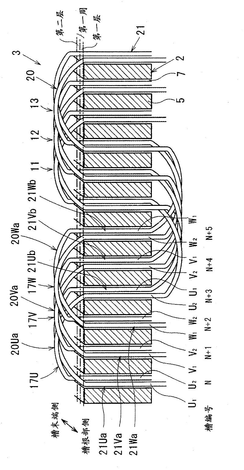
[0055] use Figure 1 to Figure 7 , the structure of the rotating electrical machine of Embodiment 1 will be described.
[0056]The rotating electrical machine of Embodiment 1 is a three-phase AC motor, and the rotating electrical machine includes a stator (armature) having a stator core 2 (armature core) and a coil wound around the stator core 2 in a distributed winding manner. Stator coil 3 (armature winding). Then, a rotating magnetic field is formed by passing a three-phase alternating current through the stator coil 3, and a rotor (not shown) arranged in the rotating magnetic field is rotated. Among them, various forms such as a permanent magnet type, an electromagnet type, and an iron core type can be employed for the rotor.
[0057] The stator core 2 is formed into a cylindrical shape by stacking a plurality of steel plates. In addition, the stator core 2 has: a plurality of teeth 5 whose ends are opposed to the rotor and arranged...
Embodiment 2
[0115] [Structure of Embodiment 2]
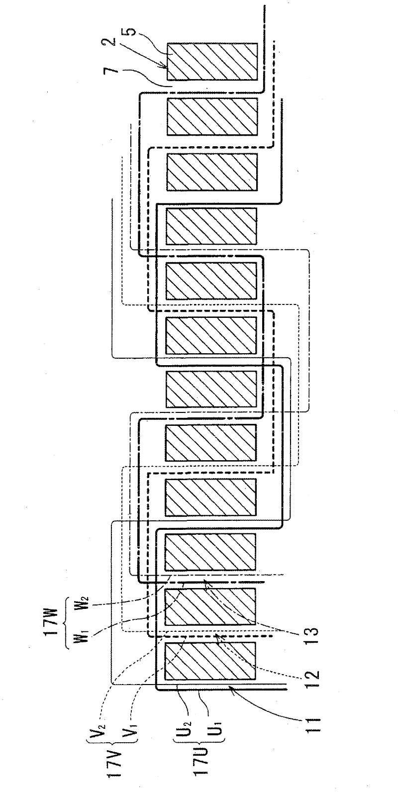
[0116] use Figure 8 , focusing on the points different from those of the first embodiment, the structure of the rotating electrical machine of the second embodiment will be described.
[0117] In the rotating electric machine of embodiment 2, the first conductor U 1 , the second conductor U 2 , the first conductor V 1 , the second conductor V 2 , the first conductor W 1 , and the second conductor W 2 The processing method in the curve portion 20 is different from that of the first embodiment.
[0118] In this embodiment, if the turning portion 20Ua is taken as an example, the first conductor U arranged in the first layer of the Nth slot 7 1 , passing through and across the upper part of the first layer of the N+1th groove 7, the upper part of the boundary part between the first layer and the second layer of the N+2th groove 7, and entering the first layer of the N+3th groove 7 second floor.
[0119] In addition, the second conduct...
Embodiment 3
[0129] [Structure of Embodiment 3]
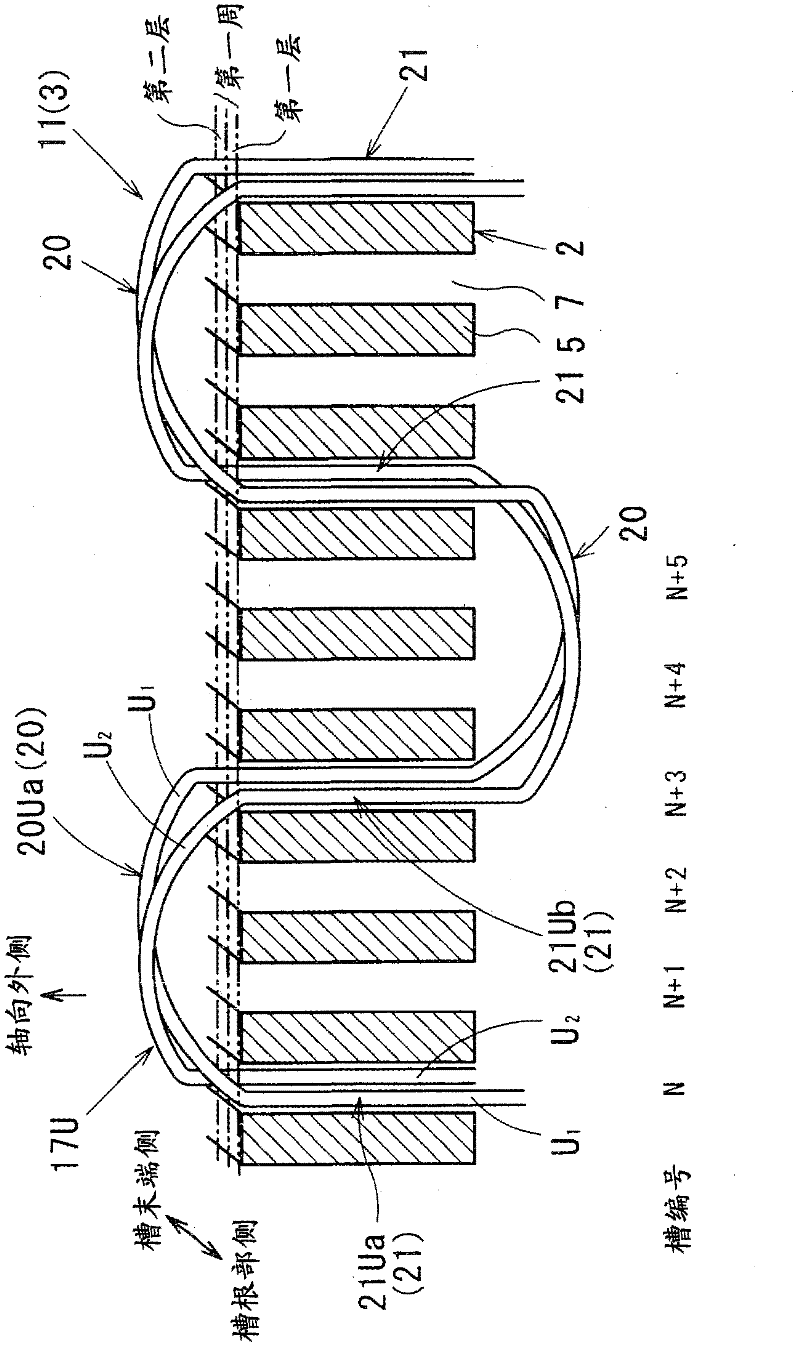
[0130] use Figure 9 , focusing on the points different from those of Embodiment 1, the structure of the rotating electrical machine of Embodiment 3 will be described.
[0131] In embodiment 3, the first conductor U 1 , the second conductor U 2 , the first conductor V 1 , the second conductor V 2 , the first conductor W 1 , and the second conductor W 2 From the start of winding to the end of winding, it is wound in a wave form in one direction in the circumferential direction of the stator core 2 .
[0132] As a result, teeth on which the stator coil 3 is not wound (empty teeth 5A) are formed on the axial end surface of the stator core 2 in accordance with the number of poles of the rotor.
[0133] Specifically, in the present embodiment, the rotor of the rotating electrical machine has 14 magnetic poles. Therefore, if Figure 9 As shown, seven teeth of the stator core 2 on which the stator coil 3 is not wound are formed on each ax...
PUM
 Abstract
Description
Claims
Application Information