
Punching die for drainage holes of stainless steel tubes

A technology of stainless steel pipes and punching dies, which is applied in the field of parts processing equipment, can solve the problems of low efficiency, low processing accuracy, and backward processing methods, and achieve the effects of less manual operations, high production accuracy, and high work efficiency

Inactive Publication Date: 2012-08-01
宁海县雁苍山电力建设有限公司 +4
View PDF8 Cites 15 Cited by
  • Summary
  • Abstract
  • Description
  • Claims
  • Application Information

AI Technical Summary

Problems solved by technology

[0002] Stainless steel pipe with rows of holes is a hardware fitting that is used more often. However, in the prior art, the processing method for such stainless steel pipes with rows of holes is still quite backward. Most of the holes are drilled by workers. drilled out
Obviously, this processing method has very low efficiency and low processing accuracy.

Method used


Image

  • Punching die for drainage holes of stainless steel tubes
  • Punching die for drainage holes of stainless steel tubes
  • Punching die for drainage holes of stainless steel tubes

Examples


Embodiment Construction

[0025] The present invention will be described in further detail below in conjunction with the accompanying drawings.

[0026] combined with Figure 4 To attach Figure 8 , a punching die for stainless steel pipe row holes, which includes an upper die and a lower die, the upper die includes a die handle 201, an upper template 202, a backing plate 203, a fixed plate 207 and a plurality of side-by-side punches 205, and a fixed plate 207 On the upper end surface of the upper end, a backing plate 203, an upper template 202 and a mold handle 201 are installed in sequence from bottom to top, and a plurality of side-by-side punches 205 are embedded in the fixed plate 207; the lower mold includes a product positioning device 301, a left positioning plate 320 , the right positioning plate 303, the lower fixing plate 317 and the base plate 316, the upper end surface of the base plate 316 is equipped with a lower fixing plate 317, the left side of the lower fixing plate 317 is equipped ...


PUM


Abstract

The invention relates to a punching die for drainage holes of stainless steel tubes, which is characterized by comprising an upper die and a lower die. The upper die comprises a die handle (201), an upper die plate (202), a cushion plate (203), a fixed plate (207) and a plurality of abreast punching heads (205). The lower die comprises a product location device (301), a left location plate (320), a right location plate (303), a lower fixing plate (317) and a bottom plate (316), wherein the lower fixing plate (317) is arranged at the upper end face of the bottom plate (316), the left location plate (320) is positioned on the left side of the lower fixing plate (317), the right location plate (303) is installed on the right side of the lower fixing plate (317), the product location device (301) is arranged on the left side of the left location plate (320), and stainless steel tube insertion holes are arranged on the right location plate (303). The punching die for drainage holes of stainless steel tubes is small in manual operation and high in production efficiency.

Description

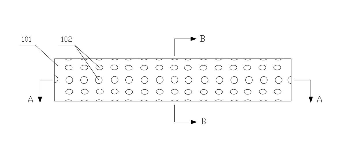
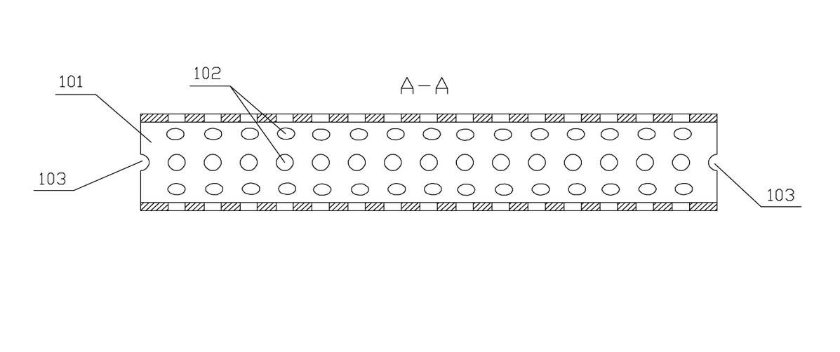
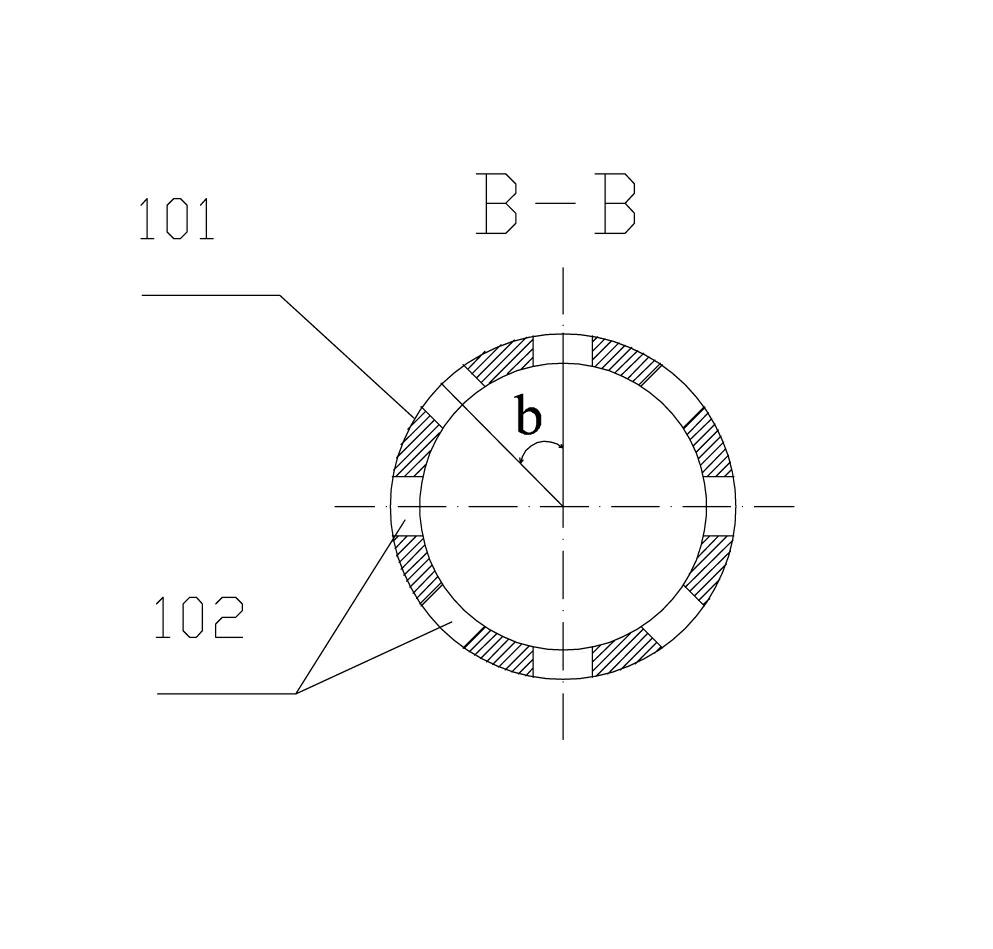
technical field [0001] The invention relates to the technical field of parts processing equipment, in particular to a punching die for stainless steel pipe row holes. Background technique [0002] Stainless steel pipe with rows of holes is a hardware fitting that is used more often. However, in the prior art, the processing method for such stainless steel pipes with rows of holes is still quite backward. Most of the holes are drilled by workers. drilled out. Obviously, this processing method has very low efficiency and low processing accuracy. to attach figure 1 to attach image 3 The shown stainless steel pipe is taken as an example, the pipe includes a pipe body 101, and 8 rows of through holes are evenly punched on the pipe body, each row of through holes has 15 holes, and these holes are collectively referred to as the row of holes 102. Just such a stainless steel pipe requires workers to drill 120 holes on it, and the spacing between each hole is required to be even...

Claims


Application Information

Patent Timeline
Patent Type & Authority Applications(China)
IPC IPC(8): B21D28/28B21D28/34B21D37/10
Inventor 陆颂荫
Owner 宁海县雁苍山电力建设有限公司
Learn More