Bidirectional rotary electric cutter rest

A tool holder and electric technology, applied in the direction of tool holders, etc., can solve problems such as looseness, loud vibration and noise, and damage to the operator's hearing

Inactive Publication Date: 2012-08-01
JIANGSU HONGDA NUMERICAL CONTROL TECH CO LTD
View PDF4 Cites 3 Cited by
  • Summary
  • Abstract
  • Description
  • Claims
  • Application Information

AI Technical Summary

Problems solved by technology

Because the coarse positioning pin can only slide up and down in the pin sleeve, and the pin sleeve is fixed in the positioning hole of the box, the coarse positioning pin has to bear a huge impact and shear force, which will cause the following problems: 1) Th

Method used


Image

  • Bidirectional rotary electric cutter rest
  • Bidirectional rotary electric cutter rest
  • Bidirectional rotary electric cutter rest

Examples


Embodiment Construction

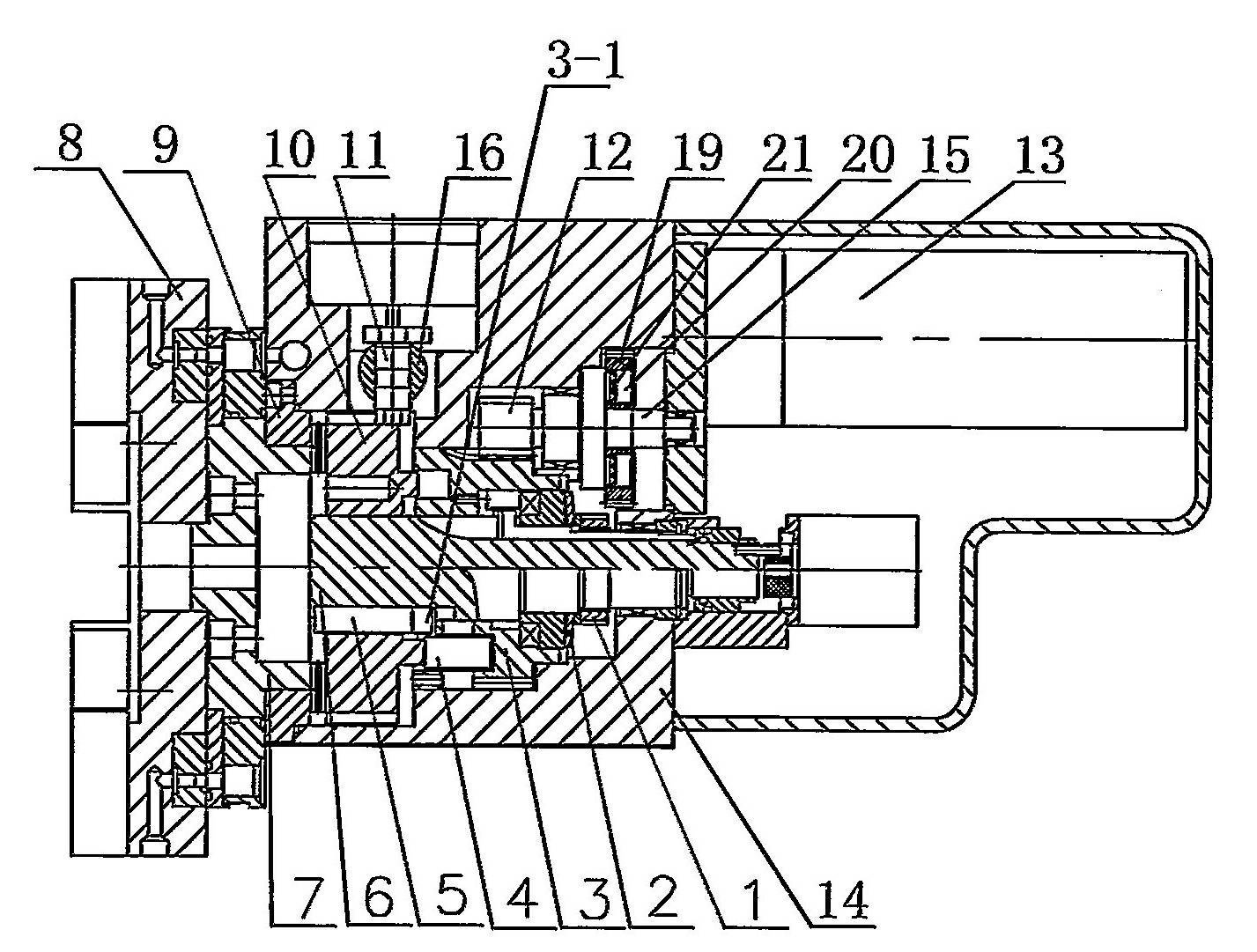
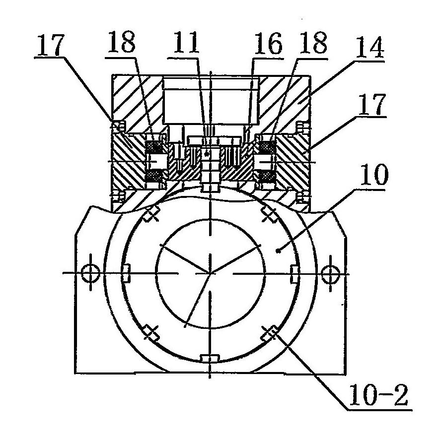
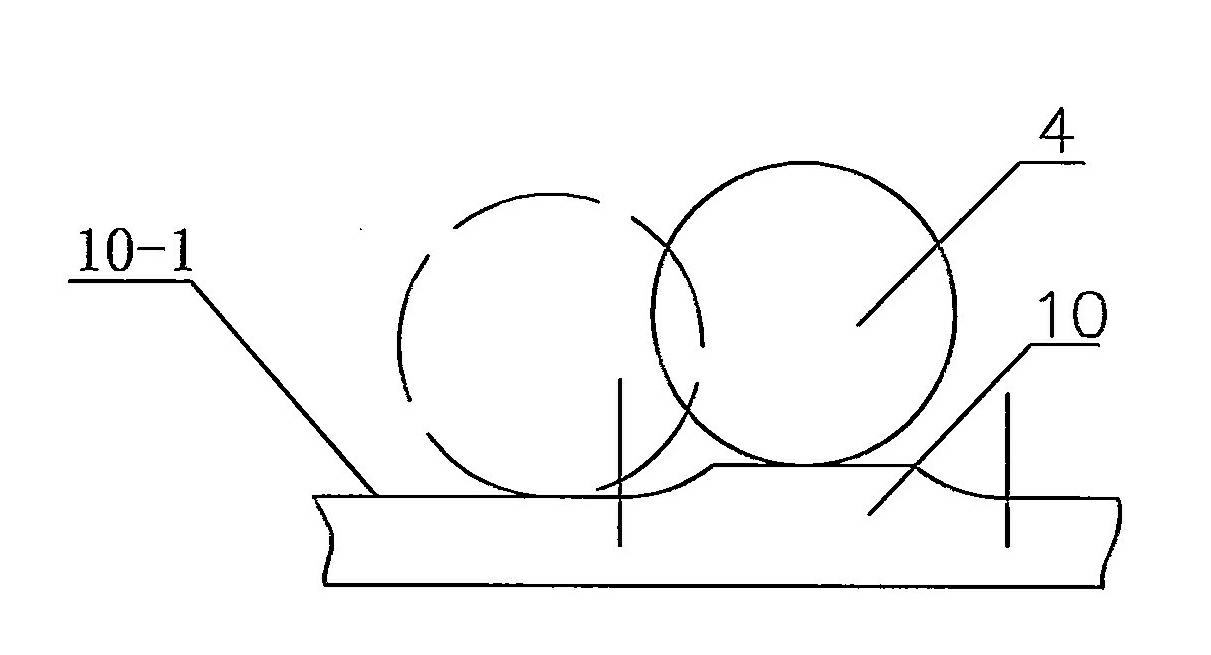
[0012] In order to make the content of the present invention easier to be understood clearly, the following further describes the present invention in detail based on specific embodiments in conjunction with the accompanying drawings.

[0013] Such as Figure 1~3 As shown, a two-way rotary electric tool post includes a box body 14, a cutter head 8, a gear shaft 15, a rotary shaft 6, a roller carrier 3, an outer gear ring 9, an inner gear ring 7 sleeved on the rotary shaft 6 and A motor 13 capable of forward and reverse rotation and a clamping ring gear 10 capable of meshing with the inner gear ring 7 and the outer gear ring 9. The gear shaft 15 is covered with a gear 12, the motor 13 drives the gear shaft 15 to rotate, and the gear 12 and the roller carrier 3 Engaged, the roller carrier 3 is rotatably supported on the rotary shaft 6 through bearings, the clamping gear ring 10 is movably sleeved on the rotary shaft 6 through the key 5, the inner gear ring 7 is fixedly connected to...


PUM


Abstract

The invention discloses a bidirectional rotary electric cutter rest. The bidirectional rotary electric cutter rest comprises a box body, a cutter head, a gear shaft, a rotary shaft, a roller carrier, an outer gear ring, an inner gear ring which is sleeved on the rotary shaft, a motor which can rotate forwardly and reversely, and a clamping gear ring which can be meshed with the inner gear ring and the outer gear ring, wherein a gear is sleeved on the gear shaft; the motor drives the gear shaft to rotate; the gear is meshed with the roller carrier; the roller carrier is supported on the rotary shaft rotatably; the clamping gear ring is moveably sleeved on the rotary shaft through a key; the inner gear ring is fixedly connected with the cutter head; the outer gear ring is fixedly connected with the box body; the bidirectional rotary electric cutter rest also comprises a primary positioning pin; the back end surface of the clamping gear ring is a step plane; a roller which can roll along the back end surface of the clamping gear ring is installed inside the roller carrier; a key slot which is matched with the key is formed on the roller carrier; and a plurality of primary positioning slots which are matched with the primary positioning pin are formed on the clamping gear ring. The bidirectional rotary electric cutter rest is high in locking speed and locking stability and low in noise.

Description

Technical field [0001] The invention relates to a two-way rotary electric tool post, which is used on an automatic rotary turret of a numerical control machine tool. Background technique [0002] At present, the automatic rotary turret of CNC machine tools is driven by a servo motor, and adopts the structure of the motor positive conversion position, coarse positioning limit, and motor reverse locking. Due to the uncertainty of the load and the error in the machining of the parts, plus the difference in electrical control, in order to ensure the reliable operation of the tool post, a certain amount of overshoot is required for the cutter head when the tool is changed forward, that is, the rough positioning pin faces straight and The positioning groove should be separated from the straight face for a certain distance. When the tool post is locked, the coarse positioning pin is pressed down under the action of the spring, and the cutter head and cutter head accessories, tools and ...

Claims


Application Information

Patent Timeline
IPC IPC(8): B23B29/32
Inventor 杨俊召吴华平
Owner JIANGSU HONGDA NUMERICAL CONTROL TECH CO LTD
Why Eureka
Try Eureka