

Adjustable anti-sliding drilling support
An adjustable, non-slip technology, applied in the field of support fixtures, can solve the problems of cumbersome operation, scratches on the surface of the steel pipe, high cost, etc., and achieves the effects of low investment cost, easy implementation and simple structure
- Summary
- Abstract
- Description
- Claims
- Application Information
AI Technical Summary
Problems solved by technology
Method used
Image

Examples
no. 1 example
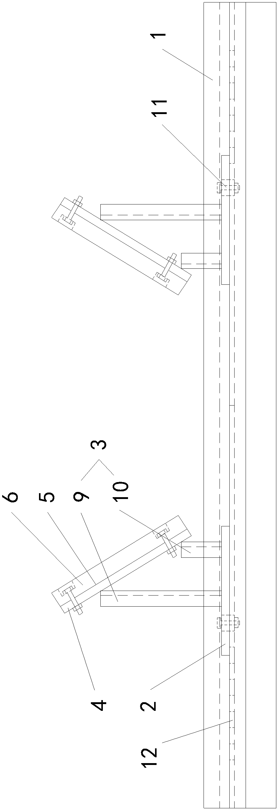
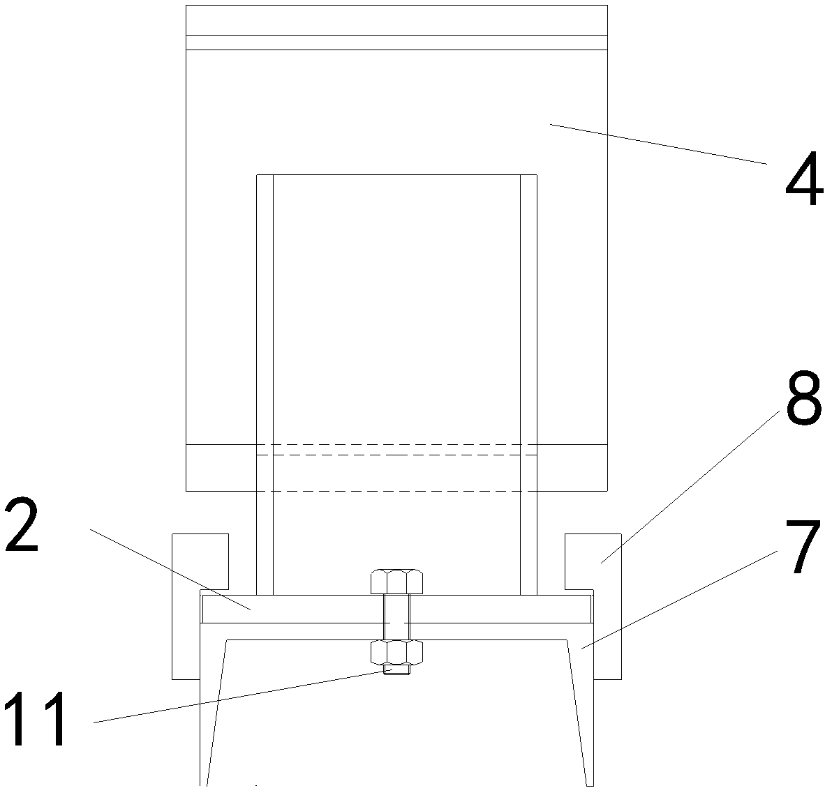
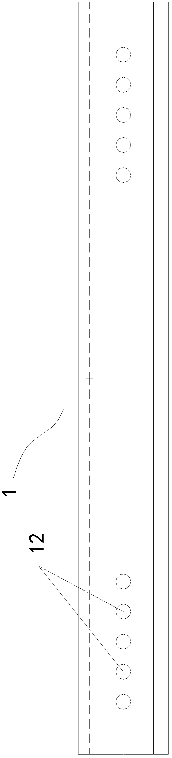
[0027] Such as figure 1 as shown, figure 1 It is a structural schematic diagram of the first embodiment of the adjustable anti-slip drilling bracket of the present invention; figure 2 for figure 1 left view of . The adjustable anti-slip drilling bracket of this embodiment includes a guide rail 1 and two supporting bodies. The support body includes a support base plate 2, a support frame 3 fixedly installed on the support base plate 2, and a spacer 4 installed on the support frame 3. The upper surface of the spacer 4 is provided with a support surface 5 for supporting the workpiece. The supporting surfaces 5 are set opposite to each other, and the included angles between the two supporting surfaces 5 and the guide rail 1 are all acute angles, that is, a V-shaped supporting structure is formed between the two supporting surfaces 5, which can be used for clamping and fixing tubular or cylindrical workpieces . The support base plate 2 is slidingly matched with the guide rail...
no. 2 example
[0035] Such as Figure 4 As shown, it is a structural schematic diagram of the second embodiment of the adjustable anti-slip drilling bracket of the present invention. The support frame 3 of the adjustable anti-slip drilling support of the present embodiment includes a long support rod 9 and a short support rod 10 fixedly installed on the support base plate 2, and the long support rod 9 and / or the short support rod 10 all adopt a telescopic rod structure, The backing plate 4 is hingedly mounted on the long support rod 9 and the short support rod 10, and the long support rod 9 and / or the short support rod 10 are provided with a locking mechanism for locking the length. Such as Figure 4 As shown, both the long support rod 9 and the short support rod 10 of this embodiment adopt a telescopic rod structure. The locking mechanism of the long support rod 9 is: correspondingly arranged on the locking hole on the sleeve rod and the core rod of the long support rod 9, when the long sup...
PUM
 Abstract
Description
Claims
Application Information