
Clamp and clamping method for large-diameter plane optical element

An optical element and large-caliber technology, applied in optical surface grinders, manufacturing tools, grinding/polishing equipment, etc., can solve problems such as optical element damage or damage growth

Active Publication Date: 2014-04-09
SHANGHAI INST OF OPTICS & FINE MECHANICS CHINESE ACAD OF SCI
View PDF4 Cites 2 Cited by
  • Summary
  • Abstract
  • Description
  • Claims
  • Application Information

AI Technical Summary

Problems solved by technology

[0002] At present, the development trend of high-power lasers is large-caliber, high-throughput, and arrayed. To achieve high-throughput laser transmission, a clean, dry, and pollution-free environment is required. The traditional stress-free clamping of organic matter is obviously not possible. meet the requirement
This is mainly because the traditional stress-free clamping method of organic matter uses silica gel, vacuum rubber or cork, etc., which will produce pollutants - aerosols under the direct or indirect irradiation of high-power lasers, which are distributed in the entire experimental environment and affect the optical components. Contamination resulting in damage or damage growth of optical components under laser irradiation

Method used


Image

  • Clamp and clamping method for large-diameter plane optical element
  • Clamp and clamping method for large-diameter plane optical element
  • Clamp and clamping method for large-diameter plane optical element

Examples


Embodiment Construction

[0040] The present invention will be further described below with reference to the embodiments and accompanying drawings, but the protection scope of the present invention should not be limited by this.

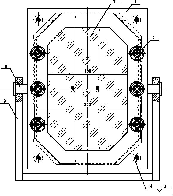
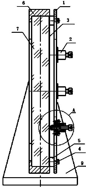
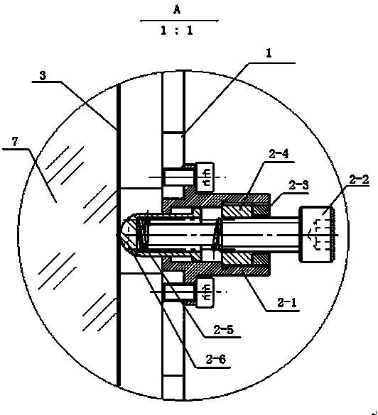
[0041] see first figure 1 , figure 1 It is a front view of the structure of the fixture of the large-diameter flat optical element of the present invention. As can be seen from the figure, the fixture of the large-diameter flat optical element of the present invention is composed of a large-diameter flat optical element pressure plate 1, an elastic fulcrum 2, a deformed thin plate frame 3, an inner Hexagon head screw 4, boss 5, mirror frame 6, rotating shaft 8 and bracket 9, the positional relationship of the above components is as follows:

[0042] The clamped large-diameter flat optical element 7 should have a certain periphery outside the clear aperture for the deformed thin-plate frame 3 to be attached. The shape of the perimeter is the same;

[0043] The said mirror f...


PUM


Abstract

Provided are a clamp and a clamping method for a large-diameter plane optical element. The clamp comprises a large-diameter plane optical element press plate, an elastic pivot, a transformation thin plate frame, an inner hexagonal cylindrical head screw, a boss, a lens frame, a rotational shaft and a support. The clamp and the clamping method utilize a metal structure to directly clamp the large-diameter optical element, can produce no optical element clamping stress under the condition that surface processing accuracy of a metal clamping frame is reduced and the optical element is in any inclination angle. Simultaneously, the metal structure is utilized to conduct direct clamping, thereby well avoiding organic pollution caused by stress-free clamping of tradition organics. The clamp the clamping method can be widely applied to clamping of the large-diameter plane optical element in optical engineering and optical experiment devices and has strong practicability.

Description

technical field [0001] The invention relates to an optical element, in particular to a clamp and a clamping method for a large-diameter plane optical element, which can be widely used in the clamping of the large-diameter plane optical element in optical engineering and optical experimental devices, especially in a vacuum environment and cleanliness. In a demanding environment, this method can also meet the clamping of various shapes and large-diameter flat optical components, and meet the requirements of no pollution and no stress. Background technique [0002] At present, the development trend of high-power lasers is large-diameter, high-throughput, and arrayed. To achieve high-throughput laser transmission, a clean, dry, and pollution-free environment is required. Traditional organic stress-free clamping is obviously impossible. meet this requirement. This is mainly because the traditional stress-free clamping method of organic materials uses silica gel, vacuum rubber or...

Claims


Application Information

Patent Timeline
Patent Type & Authority Patents(China)
IPC IPC(8): B24B13/005
Inventor 邵平居玲洁赵东峰汤更秀乔战峰
Owner SHANGHAI INST OF OPTICS & FINE MECHANICS CHINESE ACAD OF SCI
Learn More