Wave energy collecting ship

A technology of wave energy and ship bow, applied in the field of green new energy, can solve the problems of low efficiency of capturing wave energy and poor ability to resist wind and waves, and achieve the effects of improving safety, improving adaptability, and high collection efficiency

Inactive Publication Date: 2012-08-01
袁媛
View PDF10 Cites 10 Cited by
  • Summary
  • Abstract
  • Description
  • Claims
  • Application Information

AI Technical Summary

Problems solved by technology

Although Pendulum and Raft have relatively low requirements for fixed foundations, their disadvantages are low efficiency in capturing wave energy and poor wind and wave resistance

Method used


Image

  • Wave energy collecting ship
  • Wave energy collecting ship
  • Wave energy collecting ship

Examples


Embodiment Construction

[0030] In order to describe in detail the technical content and structural features of the wave energy collection ship of the present invention, the following will be further described in conjunction with the embodiments and accompanying drawings.

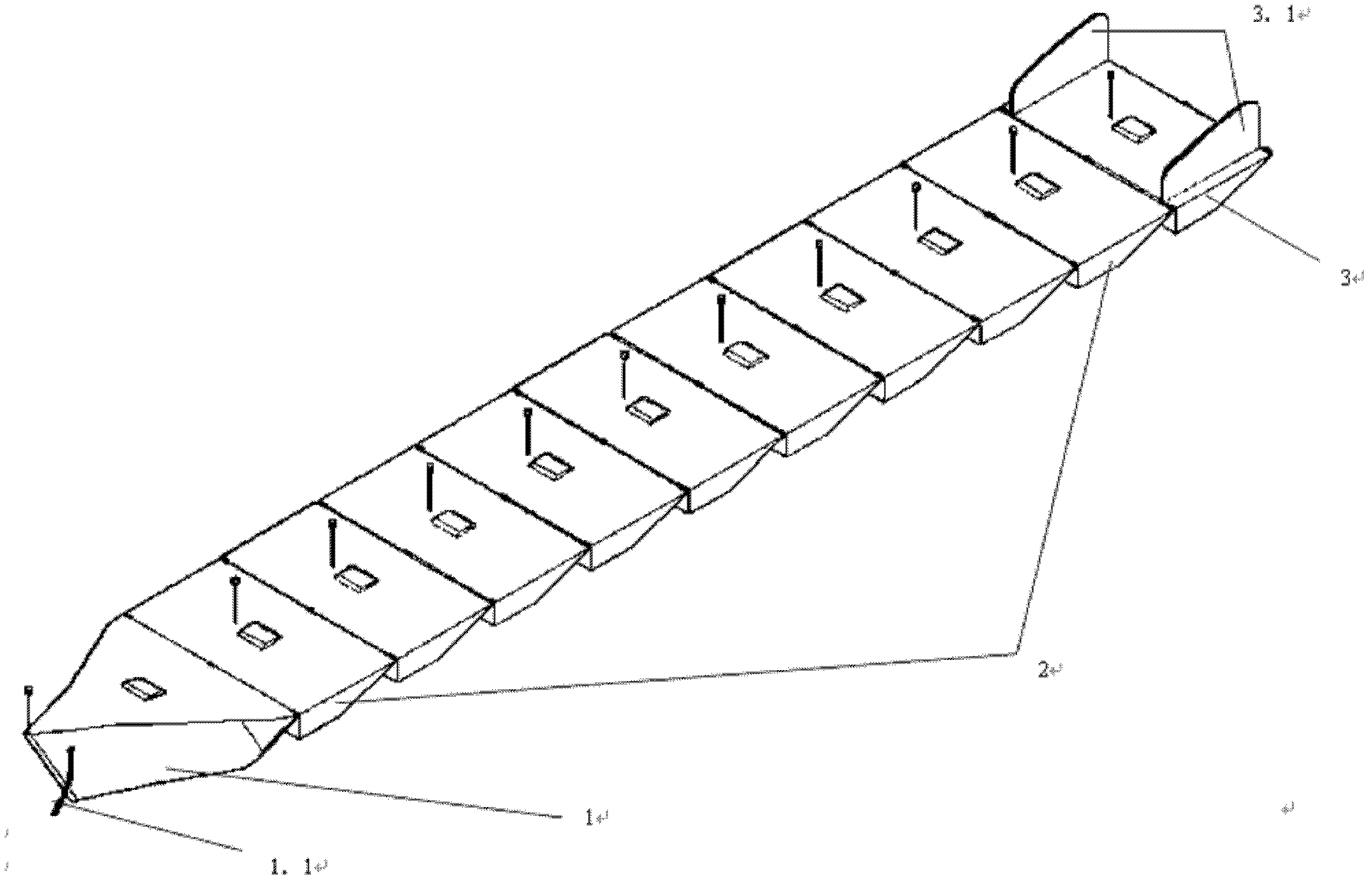
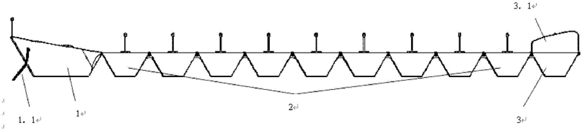
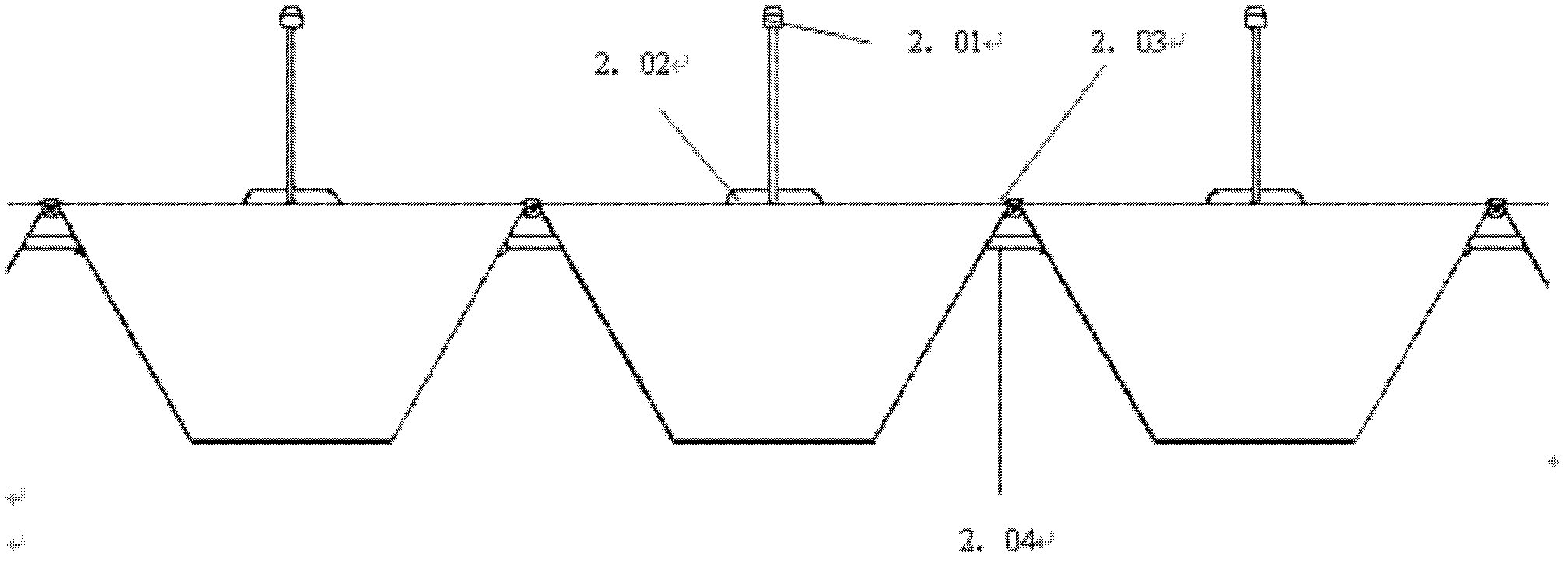
[0031] Such as figure 1 , 2 , 3, 4, 5, 6, 7, and 8, the wave energy collection ship of the present invention includes a bow floating body 1, a hull floating body 2 and a stern floating body 3; the hull floating body 2 includes at least two isosceles trapezoidal The number of floating bodies and isosceles trapezoidal floating bodies is selected according to the actual situation. Two adjacent isosceles trapezoidal floating bodies are connected by a hinge structure connecting device (1.03, 2.03, 3.03), and a hydraulic cylinder (2.04, 3.03) is arranged on one side of the hinge structure connecting device. 3.04); the wave-breaking part of the bow floating body 1 is an acute angle body, and the hull of the bow floating body 1 is fixed b...


PUM


Abstract

The invention discloses a wave energy collecting ship which is mainly formed by connecting more than two trapezoid buoys in series. According to the main working principle of the wave energy collecting ship, the trapezoid buoys are driven by wave to perform vertical bending motion; a hydraulic cylinder is arranged at an included angle for connecting two adjacent trapezoids; two adjacent buoys are bent under the fluctuation action of sea wave, so that the hydraulic cylinder at the included angle is stretched or extruded; two one-way valves are respectively connected to an oil inlet and an oil outlet of the hydraulic cylinder; the one-way valves and the hydraulic cylinder are formed into a plunger pump structure; and when the two adjacent buoys are bent for one time under the fluctuation action of the sea wave, a piston of the hydraulic cylinder is stretched for one time and oil is pumped outwards for two times by a plunger pump, so that the wave energy is collected and converted into hydraulic energy.

Description

technical field [0001] The invention relates to the field of green new energy, in particular to a wave energy collection ship. Background technique [0002] Countries have begun to adapt to local conditions and strive to find cheap energy sources available locally. For example, the United Kingdom, Japan, Norway and other countries are trying to vigorously develop wave power generation. There are many wave energy harvesting technologies at this stage, but in summary, the wave energy utilization device at this stage is mainly composed of two parts, the first part is a device for capturing wave energy, and the second part is an energy form conversion device; the forms of wave energy capture systems are: Oscillating water column (OWC), oscillating float (Buoy), pendulum (Pendulum), duck (Duck), raft (Raft), contraction ramp (Tapchan), clam (Clam), etc., in which the oscillating water column Type (OWC), oscillating float type (Buoy), etc. have higher requirements for fixed found...

Claims


Application Information

Patent Timeline
Patent Type & Authority Applications(China)
IPC IPC(8): B63B35/00F03B13/14
CPCY02E10/38Y02E10/30
Inventor 袁媛
Owner 袁媛
Why Eureka
Try Eureka