Container bottom plate and container bottom plate unit made of novel composite material for container bottom plate

A technology of container floor and composite material, applied in the field of container floor and container floor unit, can solve the problems of deformation of a single floor unit, affecting the service life of the floor, high labor intensity, etc. low intensity effect

Active Publication Date: 2013-03-20
NANTONG CIMC ECO NEW MATERIAL DEV CO LTD +1
View PDF6 Cites 0 Cited by
  • Summary
  • Abstract
  • Description
  • Claims
  • Application Information

AI Technical Summary

Problems solved by technology

[0006] 3. Installation features: Traditional wooden container floor units need to lay at least 12 floor panels in a 40-foot standard container. The installation process is to use manual or equipment to spread the floor units on the bottom frame of the box, and insert the front, rear, left, and right positions (manually) , drawing lines and drilling positioning, drilling, nailing, locking and other processes, the labor intensity is high and the efficiency is low
[0007] 4. Splicing method: The traditional container floor unit assembly method is generally to set a tenon on one side of the floor unit and "Ω"-shaped or in-line center beam or bottom side beam angle steel to be spliced ​​with each other through sealant. The method can effectively play a sealing role, but when two adjacent bottom plates are subjected to asynchronous force, a single bottom plate unit will be deformed or slightly displaced, and then form a squeeze on the adjacent bottom plate unit, resulting in Local damage or delamination at the contact position between two adjacent floor units
The traditional container bottom plate is often scrapped due to local damage at the assembly interface, which affects the service life of the bottom plate

Method used


Image

  • Container bottom plate and container bottom plate unit made of novel composite material for container bottom plate
  • Container bottom plate and container bottom plate unit made of novel composite material for container bottom plate
  • Container bottom plate and container bottom plate unit made of novel composite material for container bottom plate

Examples


Embodiment 1

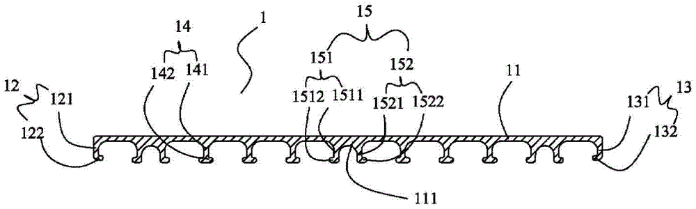
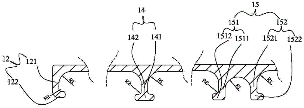
[0075] Example 1: Such as Figure 1A As shown, the container floor unit 1 according to Embodiment 1 of the present invention is made of glass fiber composite material or carbon fiber composite material or aramid fiber composite material or natural fiber composite material. The container floor unit 1 of the first embodiment includes a panel 11, two end webs 12 and 13 extending downward from the bottom of both ends of the panel 11, and a plurality of middle webs 12 and 13 extending downward from the middle bottom of the panel 11. Webs 14 and 15. Wherein, the bottoms of the two end webs 12 and 13 are in the shape of inner hooks, the end web 12 includes a vertical support 121 and an inner hook 122 bent inwardly along the vertical support 121, and the end web 13 includes A vertical support 131 and an inner hook 132 bent inwardly along the vertical support 131, the shape of the inner hooks 122 and 132 matches the horizontal supports 72 and 73 of the "Ω" ground beam, and the heigh...

Embodiment 2

[0082] Example 2: Such as Figure 2A As shown, the container floor unit 2 according to Embodiment 2 of the present invention is made of glass fiber composite material or carbon fiber composite material or aramid fiber composite material or natural fiber composite material. The difference between the container floor unit 2 of the present embodiment 2 and the container floor unit 1 of the embodiment 1 is that the middle web 25 is a vertical web, and the vertical web 25 is provided with screw holes, and the ground nails 251 correspond to the containers. Bottom beam fastening (combined with see Figure 11 shown), the rest of the structure is the same as that of Embodiment 1, and will not be repeated here. 22 and 23 among the figure are end webs, and 21 is a panel.

[0083] Such as Figure 2B As shown, when the container bottom plate unit 2 of the present embodiment 2 is laid on the container bottom frame, it is spliced ​​along the transverse direction, that is, the width dire...

Embodiment 3

[0085] Example 3: Such as Figure 3A As shown, the container floor unit 3 according to Embodiment 3 of the present invention is made of glass fiber composite material or carbon fiber composite material or aramid fiber composite material or natural fiber composite material. The difference between the container floor unit 3 of Embodiment 3 and the container floor unit 1 of Embodiment 1 is that the bottom of one of the end webs 32 is in the shape of an inner hook, that is, it includes a vertical support 321 and is supported by the vertical support 321. The inner hook 322 bent inward matches the shape of the inner hook 322 with the horizontal supports 72 and 73 of the "Ω" ground beam, while the other end web 33 is in the shape of an outer U, that is, it includes a vertical The rest of the structure of the straight support 331 and the outer U-shaped accommodating groove 332 bent outward from the vertical support 331 is the same as that of Embodiment 1, and will not be repeated he...


PUM


Abstract

The invention relates to a container bottom plate unit made of a novel composite material. The novel container bottom plate unit is made of the fiber strengthening polymer matrix composite material and comprises a panel and a plurality of webs, the bottom of the panel downwards extends to form the webs, the webs comprise two end webs located at two ends of the panel and a middle web located in the middle of the panel, and the heights of the two end webs are equal to or lower than the height of the middle web. Container bottom plate units can be in lap joint along transverse inner fasteners or / and are spliced with 'Omega'-shaped container steel center sills in a matched manner to form an total container bottom plate. The container bottom plate unit is made of the fiber strengthening polymer matrix composite material, a bottom plate unit structure and a splicing mode thereof, which correspond to the material, are adopted, and accordingly the container bottom plate unit has an excellent environmental protection performance, an excellent lightweight performance and an excellent installation performance.

Description

technical field [0001] The invention relates to a container bottom plate and a container bottom plate unit thereof, in particular to a container bottom plate unit made of fiber-reinforced polymer-based composite material and a container bottom plate spliced ​​by the container bottom plate unit. Background technique [0002] In the existing container structure, the bottom structure of the container is the main bearing part. The bottom structure of the container includes an underframe and a bottom plate laid on the underframe of the container. The underframe of the container includes two parallel and longitudinally arranged bottom side beams, several bottom cross beams arranged transversely between the two bottom side beams, and At least one mid-ground beam in the shape of "Ω" or in-line arranged longitudinally. [0003] The bottom structure of the container is the main load-bearing part of the container, so it puts forward higher requirements for the strength and good appear...

Claims


Application Information

Patent Timeline
Patent Type & Authority Patents(China)
IPC IPC(8): B65D90/02B65D90/08
Inventor 何爽彭稳王富有
Owner NANTONG CIMC ECO NEW MATERIAL DEV CO LTD
Why Eureka
Try Eureka