Hydraulic adjustable hub sling for wind-driven generator

A wind turbine, adjustable technology, applied in the directions of load hanging components, transportation and packaging, can solve the problems of difficult adjustment of the hub installation position, lack of safety and reliability, complex structure of the spreader, etc., to reduce construction costs, use Safe, reliable and accurate alignment

Inactive Publication Date: 2012-08-01
CHINA MCC17 GRP
View PDF5 Cites 5 Cited by
  • Summary
  • Abstract
  • Description
  • Claims
  • Application Information

AI Technical Summary

Problems solved by technology

[0002] The hub of the wind turbine is aligned with the blades to form the impeller, which is an important component of the wind turbine. The installation sequence of the impeller components of different types of wind turbines is different. One of the installation methods is to hoist the hub in place first, and then Then hoist the three blades separately, but before the hub is hoisted to a high altitude, the installation position of the hub needs to be adjusted so that it can be directly and accurately aligned with the engine room after being hoisted to a high altitude. It is cumbersome, difficult to adjust the installation position of the hub, and lacks safety and reliability

Method used


Image

  • Hydraulic adjustable hub sling for wind-driven generator
  • Hydraulic adjustable hub sling for wind-driven generator
  • Hydraulic adjustable hub sling for wind-driven generator

Examples


Embodiment Construction

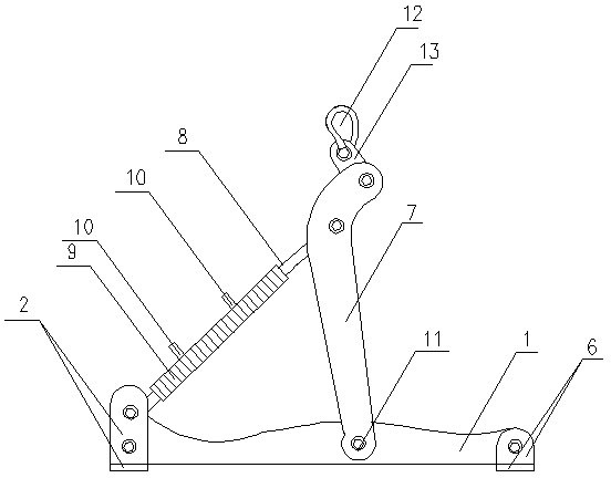
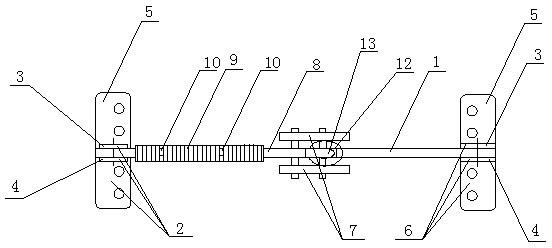
[0011] A hydraulically adjustable wind turbine hub spreader, characterized in that the hub spreader is mainly composed of a main boom 1, an adjusting arm 7, a left connecting seat plate 2, a right connecting seat plate 6, a lifting plate 13, and a shackle 12 The main boom 1 is a long strip-shaped vertical panel arranged in the left and right directions, the upper surface of the middle section is arc-shaped and convex, and the upper surfaces of the left and right ends are arc-shaped. Connecting holes are respectively set in the middle, and the connecting holes at the left end of the main boom 1 are fixed with bolts to install the left connecting seat plate 2, which is mainly composed of the bottom plate 5 and the front and rear vertical plates 4 and 3 welded together. The base plate 5 is a front-to-rear rectangular plate, and the left-right front vertical plate 4 and the rear vertical plate 3 are welded symmetrically at intervals in the middle of the base plate 5, and the bottom...


PUM


Abstract

The invention relates to a hydraulic adjustable hub sling for a wind-driven generator and belongs to a mounting sling for the wind-driven generator. The hydraulic adjustable hub sling is characterized by mainly comprising a main suspension arm, adjusting arms, a left connecting seat board, a right connecting seat board, a hoisting board and a shackle, wherein the main suspension arm is a long strip-shaped vertical panel which is laterally arranged; connecting holes are respectively formed in the left end part, the right end part and the middle of the main suspension arm; the left connecting seat board and the right connecting seat board are fixedly arranged in the connecting holes in the left end part and the right end part of the main suspension arm; the left connecting seat board and the right connecting seat board are mainly formed by welding a base plate and front vertical plates as well as rear vertical plates; holes are formed in the upper parts of the front and rear vertical plates of the left connecting seat board; hydraulic oil cylinders are hinged in the holes of the front and rear vertical plates of the left connecting seat board by pin rolls; two bolt holes are respectively formed in the base plate; front and rear adjusting arms are hinged in the connecting hole in the middle of the main suspension arm by using pin rolls; holes are formed in the upper sections of the front and rear adjusting arms; a piston rod is hinged in the holes of the front and rear adjusting arms by using pin rolls; holes are formed in the upper end sections of the front and rear adjusting arms; the hoisting plate is hinged in the holes in the upper end sections of the front and back adjusting arms by using pin rolls; the shackle is arranged on the hoisting plate; and the mounting angle of a hub is adjusted to be accurately aligned with a cabin.

Description

technical field [0001] The invention belongs to a wind power generator installation hanger, in particular to a wind power generator hub hanger. Background technique [0002] The hub of the wind turbine is aligned with the blades to form the impeller, which is an important component of the wind turbine. The installation sequence of the impeller components of different types of wind turbines is different. One of the installation methods is to hoist the hub in place first, and then Then hoist the three blades separately, but before the hub is hoisted to a high altitude, the installation position of the hub needs to be adjusted so that it can be directly and accurately aligned with the engine room after being hoisted to a high altitude. It is cumbersome, difficult to adjust the installation position of the hub, and lacks safety and reliability. Contents of the invention [0003] The purpose of the present invention is to propose a hydraulically adjustable wind turbine hub han...

Claims


Application Information

Patent Timeline
IPC IPC(8): B66C1/10B66C13/08
Inventor 徐惠杨兆林
Owner CHINA MCC17 GRP
Why Eureka
Try Eureka