Loom beating-up force control system and method

A technology for machine beating-up force and control system, which is applied in the field of textile machine beating-up force control system and textile machine beating-up force control field, can solve problems such as driving marks and parking gears, and achieve the effect of low cost.

Inactive Publication Date: 2014-02-26
ZHEJIANG SUPCON ELECTRICAL
View PDF6 Cites 0 Cited by
  • Summary
  • Abstract
  • Description
  • Claims
  • Application Information

AI Technical Summary

Problems solved by technology

[0005] The first object of the present invention is to provide a method for controlling the beating force of a textile machine, so as to solve the technical problems in the prior art that driving marks and parking gears are easily generated when the machine is switched on and off.
[0006] The second object of the present invention is to provide a textile machine beating force control system to solve the technical problems in the prior art that easily produce driving marks and parking gears when the machine is turned on and off

Method used


Image

  • Loom beating-up force control system and method
  • Loom beating-up force control system and method
  • Loom beating-up force control system and method

Examples


Embodiment Construction

[0025] The present invention will be described in detail below in conjunction with the accompanying drawings.

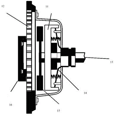
[0026] The reed of the loom is connected to the main shaft of the loom with a clutch brake system through a series of complex mechanical structures, thereby converting the rotational motion of the main shaft into the reciprocating motion of the reed. This is a common mechanism on existing looms, so it will not be described in detail. The weft yarn enters the weaving mouth through the opening of the heald frame, and then the reed reciprocates to drive the newly entered weft yarn into the woven cloth. In this circular motion, the new weft yarn is continuously driven into the weaving mouth by the reed. And then produce a complete cloth.

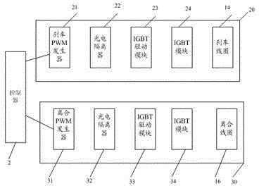
[0027] The specific working process of preventing driving marks and parking gears is as follows:

[0028] A very important link in the forming of the cloth is that the reed's reciprocating motion drives the weft yarn newly entering t...


PUM


Abstract

The invention relates to a loom beating-up force control system and a loom beating-up force control method. The method comprises the steps that pulse width modulation (PWM) brake control and PWM clutch control are respectively arranged on brake and clutch subsystems of a loom; and when a cloth face bad set mark and a stop mark are detected to be light filling bars, the PWM duty cycle of a PWM generator on the side of a clutch is increased, stronger pulse current which goes through PWM is formed on a clutch coil, suction force between a friction disc and a flywheel is increased, the PWM duty cycle of a PWM generator on the side of a brake is reduced and even is not generated, no current or weaker pulse current passes through a brake coil and the magnitude of beating-up force during startup / shutdown of the loom is adjusted. By adopting the scheme, the system structure of the loom is not modified, any mechanical components are not added, engineering realization fully focuses on a loom control system but not the loom, and by introducing PWM current in brake and clutch systems, the sliding friction of the brake and clutch systems is adjusted and brake torque and startup torque are changed. By adopting the scheme, not only can the problems of the bad set mark and the stop mark be solved, but also the realization cost is very low.

Description

technical field [0001] The invention relates to the field of textile control, in particular to a method for controlling the beating force of a textile machine and a control system for the beating force of a textile machine. Background technique [0002] In the textile field, the restart of the loom after stopping due to various reasons such as warp breaks, weft breaks, and hand stop will more or less affect the cloth surface. In the customary sense, they are called driving marks and parking gears, which are also weaving. Fields of the world puzzle. The main reasons for the driving marks and parking gears are the inconsistency of the beating force of the cloth surface when driving and parking, and the uncertain changes of various physical quantities during the parking process. Specifically, when the system brakes, the beating-up force of the last weft yarn will inevitably be insufficient due to the brake. In the same principle, after the clutch is engaged, the speed of the m...

Claims


Application Information

Patent Timeline
Patent Type & Authority Patents(China)
IPC IPC(8): D03D51/00
Inventor 李波金崇程戴岳尧胡协和
Owner ZHEJIANG SUPCON ELECTRICAL
Why Eureka
Try Eureka