Single-driving system of washing machine

A washing machine, single-drive technology, applied in other washing machines, washing devices, textiles and papermaking, etc., can solve the problems of erosion of impurities, short service life, noise and so on

Inactive Publication Date: 2012-08-01
CHANGZHOU XINYA ELECTROMOTOR
View PDF8 Cites 41 Cited by
  • Summary
  • Abstract
  • Description
  • Claims
  • Application Information

AI Technical Summary

Problems solved by technology

This patent adopts the clutch device of electromagnetic clutch principle, which has the advantages of small size and convenient operation. However, because its clutch device 131 is located between the rotor and the lower part of the bearing housing 130, the whole is located inside the motor. In the washing machine with harsh environment, and the motor is a non-sealed structure, the coupling 133 in the electromagnetic clutch device is easily eroded by water and other impurities, thus easily leading to clutch failure. The electric motor itself generates heat due to the energized stator coil winding, which causes the pull-in voltage required by the electromagnetic clutch device to be too high. Since the pull-in voltage is preset, it is easy to cause clutch failure; in addition, because the coupling described in this patent 133 collides with the bearing shell 130 when it moves upwards, which not only produces obvious noise, but also in the washing condition, because the coupling 133 and the bearing shell 130 are only fixed by mutual friction, not only the fixation is unstable, And the coupling part 133 and the bearing shell 130 that are in contact with each other and rubbing against each other experience a long period of mutual wear and tear, resulting in a short service life.

Method used


Image

  • Single-driving system of washing machine
  • Single-driving system of washing machine
  • Single-driving system of washing machine

Examples


Embodiment 1

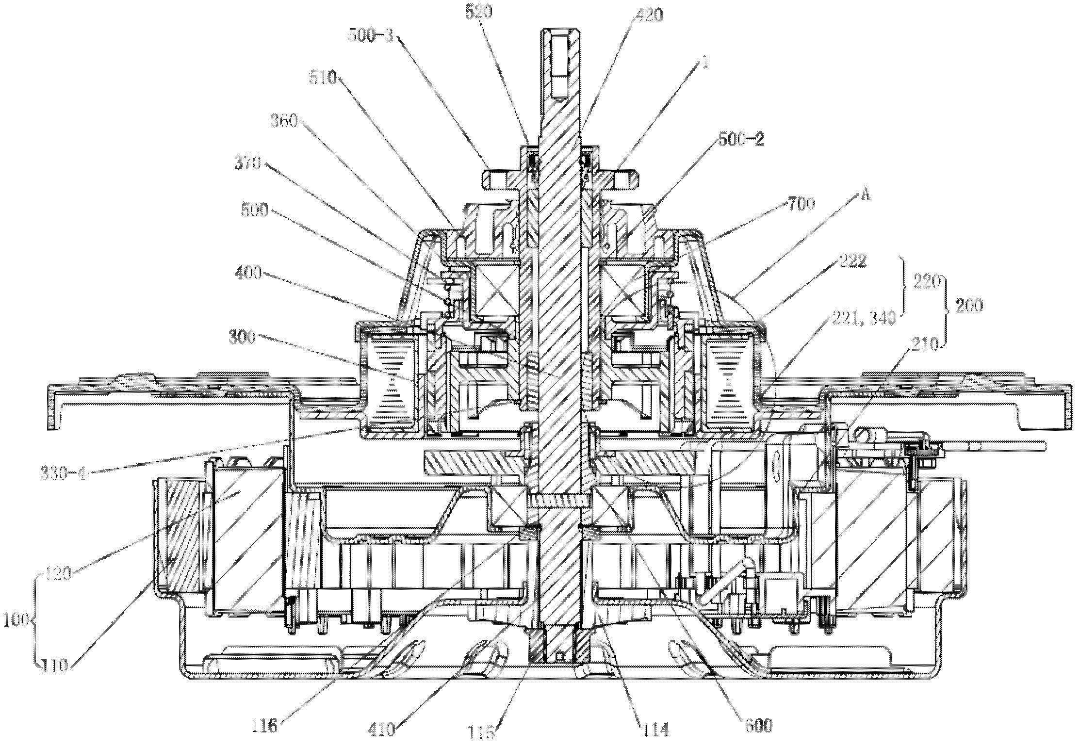
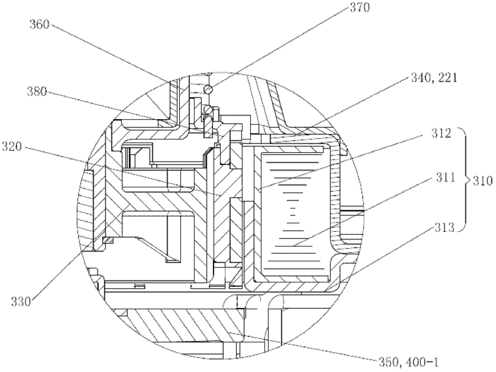
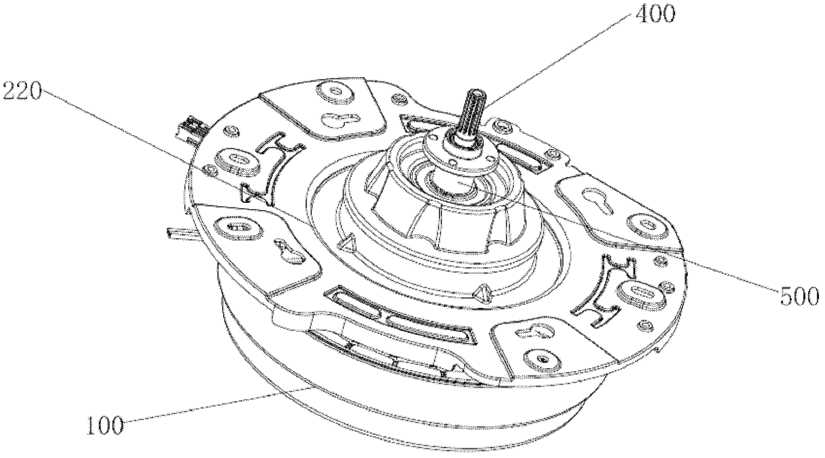
[0106] Embodiment 1, as Figure 1-5 , Figure 11 As shown, combined with other related drawings, a single drive system of a washing machine includes a motor 100, a housing 200, a clutch mechanism 300, a drive shaft 400, and a drive sleeve 500. There are two oil bearings 1 to realize that the drive shaft 400 is rotatably arranged in the drive shaft sleeve 500, the input end of the drive shaft 400 is connected with the motor 100, the output end of the drive shaft 400 is connected with the wave wheel or agitator of the washing machine, and the drive shaft sleeve 500 The output end is fixedly connected to the inner tub of the washing machine, and the clutch mechanism 300 is located inside the casing 200, wherein:

[0107] The drive shaft 400 includes a drive input shaft 410 and a drive output shaft 420, the drive input shaft 410 and the drive output shaft 420 are coaxial, that is, a single power direct drive system, which is applied to a single drive direct drive washing machine;...

Embodiment 2

[0111] Embodiment 2, as Image 6 , Figure 7 , Figure 11 As shown, and in combination with other related drawings, a single drive system of a washing machine, wherein: the drive shaft 400 includes a drive input shaft 410 and a drive output shaft 420, and the drive input shaft 410 and the drive output shaft 420 are not coaxial, A reduction gear transmission mechanism 800a is arranged between the drive input shaft 410 and the drive output shaft 420, which is a single-power reduction drive system, which is applied to a single-drive reduction washing machine. The reduction gear transmission mechanism 800a includes a sun gear 810a, five The planetary gear 820a, the inner ring gear 830a, the planetary gear cage 840a, the inner ring gear 830a is used as the meshing part 330, the clutch ring gear 320 is meshed and socketed outside the inner ring gear 830a, and the clutch ring gear 320 can move up and down along the inner ring gear 830a Moving, the sun gear 810a is fixedly arranged ...

Embodiment 3

[0112] Embodiment 3, as Figure 8-11 As shown, combined with other related drawings, a double drive system of a washing machine, which includes a motor 100, a housing 200, a clutch mechanism 300, a drive shaft 400, a drive sleeve 500, and the drive shaft 400 and the drive sleeve 500 Two oil-impregnated bearings 1 are arranged in between to realize that the drive shaft 400 is rotatably arranged in the drive shaft sleeve 500, the input end of the drive shaft 400 is connected with the motor 100, the output end of the drive shaft 400 is connected with the wave wheel or agitator of the washing machine, and the drive shaft The output end of the sleeve 500 is fixedly connected to the inner tub of the washing machine, and the clutch mechanism 300 is located inside the casing 200, wherein:

[0113] The drive shaft 400 includes a drive input shaft 410 and a drive output shaft 420, the drive input shaft 410 and the drive output shaft 420 are coaxial, and a double drive gear transmission ...


PUM


Abstract

The invention relates to a single-driving system of a washing machine, which comprises a motor, a shell, a clutch mechanism, a driving shaft and a driving shaft sleeve. The driving shaft is rotatably arranged in the driving shaft sleeve, the motor is an outer rotor motor, the shell comprises a lower shell and an upper shell which are fixedly connected, the lower shell is used as a stator retainer of an inner stator, the stator retainer is fixedly connected with the inner stator, the clutch mechanism is located in an inner space, the lower shell and the upper shell are fixedly connected to form the inner space, the clutch mechanism comprises an electromagnetic coil mechanism, a clutch gear ring, a meshing component, an upper matching component and a lower matching component, a mounting plate is used as the upper matching component, the driving shaft located above the stator retainer is fixedly connected with a clutch gear disc, the clutch gear disc is used as the lower matching component, and the clutch gear ring vertically moves along the meshing component and selectively matches with the mounting plate and the clutch gear disc. The single-driving system of the washing machine is fine in clutch performance, low in manufacturing cost and noise, convenient in installation and quite suitable for popularization and application in production.

Description

technical field [0001] The invention relates to a single driving system of a washing machine, which is suitable for use in a drum type washing machine, a wave wheel type washing machine and an agitating type washing machine. Background technique [0002] The driving system of the washing machine in the prior art mainly includes a motor, a housing, a clutch mechanism, a drive shaft, and a drive shaft sleeve, wherein the drive shaft is rotatably arranged in the drive sleeve, its lower end is connected with the motor, and its upper end is connected with the washing machine pulsator. Or the agitator is connected, and the drive shaft sleeve is fixedly connected with the inner tub of the washing machine. The clutch mechanism is connected with the motor, and is used to control whether the output power of the motor is transmitted to the drive shaft sleeve. It can also include a gear transmission mechanism, the gear transmission mechanism is arranged between the drive shaft and the ...

Claims


Application Information

Patent Timeline
Patent Type & Authority Applications(China)
IPC IPC(8): D06F37/30D06F37/20
Inventor 张咏玉林谦元
Owner CHANGZHOU XINYA ELECTROMOTOR
Why Eureka
Try Eureka