Supercharge Your Innovation With Domain-Expert AI Agents!

Motorcompressor unit with variable aerodynamic profile

A technology of electric compressors and compressors, applied in engine manufacturing, machines/engines, liquid fuel engines, etc., can solve problems such as limiting the application range of compressors

Inactive Publication Date: 2012-08-01
塞莫丁公司
View PDF7 Cites 0 Cited by
  • Summary
  • Abstract
  • Description
  • Claims
  • Application Information

AI Technical Summary

Problems solved by technology

Now, having a hole in the compressor housing greatly limits the range of compressor applications, which still falls into the low pressure, or some medium pressure range, which means pressures below about 20 bar

Method used


Image

  • Motorcompressor unit with variable aerodynamic profile
  • Motorcompressor unit with variable aerodynamic profile
  • Motorcompressor unit with variable aerodynamic profile

Examples


Embodiment Construction

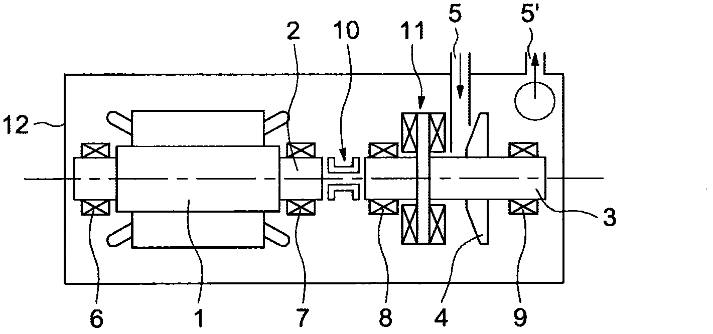
[0024] exist figure 1 The motor-compressor unit illustrated in , basically comprises an electric motor 1 , including for example a variable speed motor that drives in rotation a rotor 2 , which itself drives at the same speed a propeller shaft 3 , on which is fixed an impeller 4 .

[0025] It can be seen that the electric compressor unit thus comprises a single compression stage consisting of a centrifugal impeller 4 which sucks in the gas released from the supply pipe 5 to increase its pressure and deliver it to the outlet 5'.

[0026] In the described embodiment, the rotor 2 is supported by two end bearings 6 and 7 . The same applies to the housing of the transmission shaft 3 , which is likewise supported by two end bearings 8 and 9 . Thus, with such an arrangement, the rotor 2 and the propeller shaft 3 are connected by the flexible coupling 10 .

[0027] However, even if the rotor and drive shaft are connected by a fixed coupling, it still does not depart from the scope o...


PUM


Abstract

This motorcompressor unit comprises at least one motor driving the rotation of a rotor and at least one compression stage comprising a set of bladed impellers mounted on a driven shaft the rotation of which is driven by the rotor, the assembly consisting of the motor and the or each compressor being mounted in a common casing that is gastight with respect to the gas handled by the compressor unit. At least one of the compression members comprises at least one aerodynamic member (13) for regulating the angle at which the gas handled by the said stage flows and a motor (16) for controlling the regulating member (13) mounted in the common casing.

Description

technical field [0001] The present invention relates to centrifugal motor compressor units and, more particularly, to integral centrifugal compressor units in which the compressor and the motor means for driving the compressor are secured in a common housing which seals the gas processed by the compressor . Background technique [0002] A conventional integral compressor unit comprises an electric motor arrangement, usually consisting of an electrically driven motor, and a centrifugal compressor comprising one or more compression stages depending on the application. [0003] Each compression stage consists of an impeller mounted on a drive shaft driven by a rotor, which itself is driven by an electric motor. [0004] In some applications, and especially in low pressure applications, it has been proposed to include vanes with variable pitch blades, thus modifying the work done by the compression stages to suit the gas flow rate. [0005] In order to improve the orientation ...

Claims


Application Information

Patent Timeline
IPC IPC(8): F04D25/06F04D29/00
CPCF04D29/4206F04D29/462F04D27/0215F04D25/06F04D27/0246F05D2250/51F05D2250/52F04D29/563
Inventor G·诺洛基
Owner 塞莫丁公司
Features
  • R&D
  • Intellectual Property
  • Life Sciences
  • Materials
  • Tech Scout
  • Unparalleled Data Quality
  • Higher Quality Content
  • 60% Fewer Hallucinations
Learn More