Welded connection structure of bellows and joints

A welding connection and bellows technology, which is applied in the direction of hose connection devices, pipes/pipe joints/pipes, mechanical equipment, etc. Solving problems such as uneven welding and melting, to achieve the effect of convenient and fast installation, improved quality and yield, and simple structure

Inactive Publication Date: 2012-08-01
昆山振昆纳米科技有限公司
View PDF6 Cites 4 Cited by
  • Summary
  • Abstract
  • Description
  • Claims
  • Application Information

AI Technical Summary

Problems solved by technology

[0003] The connection structure of each bellows in China is relatively complicated, which affects the mass production of bellows, especially the existing welded metal bellows. The main purpose of welded metal bellows in China is that the equipment requires a vacuum environment or has vibration isolation. Environment, or special gas isolation, is also often used in semiconductor equipment, optoelectronic equipment, vacuum precision instruments, exhaust equipment, analytical instruments, nuclear energy-related equipment, accelerators, medical equipment, inspection equipment, etc. At present, there is no manufacturing technology in China. The hose imported from abroad is welded and repaired in China. However, due to the difference between the thickness of the bellows and the structure of the joint when the existing bellows and joints are welded, it is easy to cause uneven welding melting, poor sealing, and unstable welding structure. Installation Inconvenient and high defective rate, affecting the tensile shrinkage of bellows and the service life of bellows

Method used


Image

  • Welded connection structure of bellows and joints
  • Welded connection structure of bellows and joints
  • Welded connection structure of bellows and joints

Examples


Embodiment Construction

[0014] In order to make the technical means, creative features, goals and effects achieved by the present invention easy to understand, the present invention will be further described below in conjunction with specific embodiments.

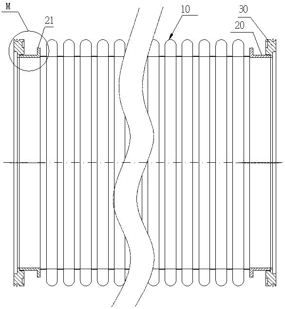
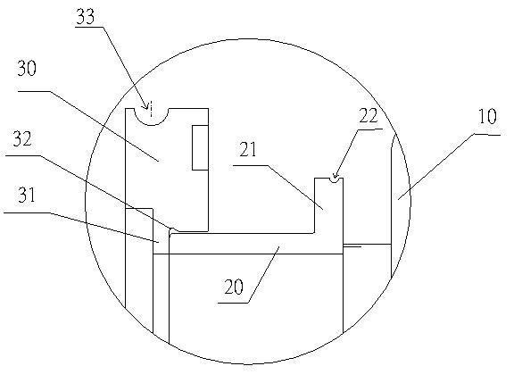
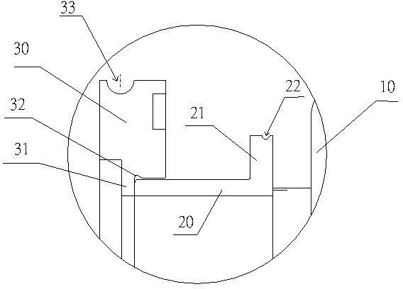
[0015] see figure 1 with figure 2 , the welded connection structure between the bellows and the joint of the present embodiment, which includes the bellows 10 and the caliper flange joint 21, and the two ends of the bellows 10 are respectively welded with inserting straight pipes 20, and one end of the inserting straight pipe 20 A welding boss 21 for connecting the end of the bellows is provided. The welding boss 21 is integrated with the plug-in straight pipe 20. On the outer surface of the welding boss 21, a position close to the connecting end of the bellows is processed with a longitudinal section that is half Circular arc groove 22, the arc groove 22 radius is 0.7mm, and the distance between it and the end face of the bellows 10 is 0.5mm, w...


PUM


Abstract

The invention relates to a welded connection structure of a bellows and joints. The welded connection structure comprises the bellows and the calipers flange joints, wherein inserted straight pipes are respectively welded at the two end parts of the bellows; one ends of the inserted straight pipes are provided with welding bosses used for being connected with one end part of the bellows, and the other ends of the inserted straight pipes are connected with the calipers flange joints; arc-shaped grooves are arranged in positions in the surfaces of the welding bosses, which are close to the connecting ends of the bellows; butting bosses butted with the end parts of the inserted straight pipes are arranged on the inner walls of the calipers flange joints; and inward concaved ear grooves are arranged in bent positions in the inner walls of the butting bosses and the calipers flange joints. By adopting the welded connection structure, the welding firmness is increased; besides, the arc-shaped grooves are arranged in the welding bosses, so an original welding rod is evenly and uniformly welded and melted during welding, the tension contractility of the bellows is increased and the quality yield is improved; and the welded connection structure has the advantages of convenience and rapidity in mounting, simpleness in structure, safety, reliability, low maintenance cost, steadiness in connection, high sealing performance and long service life, and is suitable for volume production.

Description

technical field [0001] The invention relates to a corrugated pipe, in particular to a welded connection structure between a corrugated pipe and a joint. Background technique [0002] As sensitive components, shock absorbing components, compensation components, sealing components, valve components and pipeline connectors, metal bellows are widely used in automatic control and measuring instruments, vacuum technology, machinery industry, electric power industry, transportation and atomic energy industry and other fields . The existing metal bellows connection methods are divided into flange connection, welding, threaded connection, and quick joint connection. Small-diameter metal hoses are generally connected by threaded joints and quick joints, and larger-diameter metal hoses are generally connected by flange connection and welding. [0003] The connection structure of each bellows in China is relatively complicated, which affects the mass production of bellows, especially t...

Claims


Application Information

Patent Timeline
Patent Type & Authority Applications(China)
IPC IPC(8): F16L33/28F16L33/26
Inventor 阮佳龙康进昌罗讷纳唐新荣
Owner 昆山振昆纳米科技有限公司
Why Eureka
Try Eureka