Calipers flange welded type bellows

A flange welding and bellows technology, applied in the direction of pipes/pipe joints/fittings, hose connection devices, mechanical equipment, etc., can solve the problems of high engineering cost and defective rate, inconvenient installation, poor sealing, etc. Improve quality yield, easy and fast installation, and increase the effect of tension and shrinkage

Inactive Publication Date: 2012-08-01
昆山振昆纳米科技有限公司
View PDF7 Cites 0 Cited by
  • Summary
  • Abstract
  • Description
  • Claims
  • Application Information

AI Technical Summary

Problems solved by technology

[0003] The connection structure of each bellows in China is relatively complicated, which affects the mass production of bellows, especially the existing welded metal bellows. The main purpose of welded metal bellows in China is that the equipment requires a vacuum environment or has vibration isolation. Environment, or special gas isolation, is also often used in semiconductor equipment, optoelectronic equipment, vacuum precision instruments, exhaust equipment, analytical instruments, nuclear energy-related equipment, accelerators, medical equipment, inspection equipment, etc. At present, there is no manufacturing technology in China. The hose imported from abroad is welded and repaired in China, but when the bellows and the joint are welded, it is easy to cause uneven welding melting, poor sealing, more complicated structure, inconvenient installation, high engineering cost and high defective rate, which affects the corrugation Tube tensile shrinkage and service life of bellows

Method used


Image

  • Calipers flange welded type bellows
  • Calipers flange welded type bellows
  • Calipers flange welded type bellows

Examples


Embodiment Construction

[0015] In order to make the technical means, creative features, goals and effects achieved by the present invention easy to understand, the present invention will be further described below in conjunction with specific embodiments.

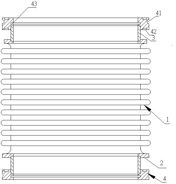
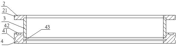
[0016] see figure 1 and figure 2 , a caliper flange welded bellows in this embodiment, which includes a bellows 1, a connecting end provided at both ends of the bellows 1, and a caliper flange 4 connected to the connecting end, and the thickness of the bellows 1 is 0.15-0.20mm , the length is 136mm. The connecting end of the present embodiment is a straight pipe 3, and one end of the straight pipe 3 is provided with a welding step 2. It is welded with the straight pipe 3 to connect the card platform, and the outer surface of the welding step 2 is processed with a small annular groove 21 near the first port of the welding step 2. The cross section of the annular groove 21 is semicircular, and its radius is 0.5mm. The distance between the annula...


PUM


Abstract

The invention relates to a calipers flange welded type bellows, which comprises the bellows, connecting ends arranged at the two ends of the bellows, and calipers flanges connected with the connecting ends, wherein the connecting ends are provided with straight pipes; a welding step is arranged at one end of each straight pipe, and the other ends of the straight pipes are connected with the calipers flanges; seam parts of the calipers flanges and the straight pipes are welded to form a whole through argon arc welding; clamping platforms used for being connected with the end parts of the other ends of the straight pipes and inner ring-shaped grooves are arranged on the inner sides of the calipers flanges; and an outer ring-shaped groove is arranged at the end part of one end of each calipers flange. The calipers flange welded type bellows has the advantages that through connecting the calipers flanges with the straight pipes and welding the calipers flanges and the straight pipes through argon arc welding, the welding and melting evenness and uniformity are realized during welding, the tension contractility of the bellows is increased and the quality yield is improved; and the calipers flange welded type bellows has the advantages of convenience and rapidity in the whole mounting process, safety, reliability, low maintenance cost, steadiness in connection and high sealing performance, the welding firmness is increased, vacuum surface deformation caused by the welding is avoided, and the calipers flange welded type bellows is suitable for volume production.

Description

technical field [0001] The invention relates to a bellows, in particular to a caliper flange welded bellows. Background technique [0002] As sensitive components, shock absorbing components, compensation components, sealing components, valve components and pipeline connectors, metal bellows are widely used in automatic control and measuring instruments, vacuum technology, machinery industry, electric power industry, transportation and atomic energy industry and other fields . The existing metal bellows connection methods are divided into flange connection, welding, threaded connection, and quick joint connection. Small-diameter metal hoses are generally connected by threaded joints and quick joints, and larger-diameter metal hoses are generally connected by flange connection and welding. [0003] The connection structure of each bellows in China is relatively complicated, which affects the mass production of bellows, especially the existing welded metal bellows. The main p...

Claims


Application Information

Patent Timeline
Patent Type & Authority Applications(China)
IPC IPC(8): F16L33/28F16L33/26
Inventor 阮佳龙康进昌罗讷纳唐新荣
Owner 昆山振昆纳米科技有限公司
Why Eureka
Try Eureka