Backlight module and liquid crystal display device comprising same

A backlight module and backplane technology, which is applied to lighting devices, fixed lighting devices, components of lighting devices, etc., can solve the problems of long heat transfer paths, affecting the service life of components, and the service life of safe liquid crystal panels, avoiding the Stability, improve the stability and service life of components, and reduce the effect of temperature

Inactive Publication Date: 2012-08-01
SHENZHEN CHINA STAR OPTOELECTRONICS TECH CO LTD
View PDF8 Cites 12 Cited by
  • Summary
  • Abstract
  • Description
  • Claims
  • Application Information

AI Technical Summary

Problems solved by technology

However, under this setting, although the influence of heat on components such as the reflective sheet 110 is avoided as far as possible during heat transfer, the heat conduction path is still to transfer heat to the backplane 100 through the heat conducting plate 190, and realize heat dissipation through the contact between the backplane 100 and the air. , the heat transfer path is still long, so the heat will still accumulate inside the backlight module for a long time, thus affecting the service life and safety of the components inside the backlight module and the service life of the liquid crystal panel of the liquid crystal display device

Method used


Image

  • Backlight module and liquid crystal display device comprising same
  • Backlight module and liquid crystal display device comprising same
  • Backlight module and liquid crystal display device comprising same

Examples


Embodiment 1

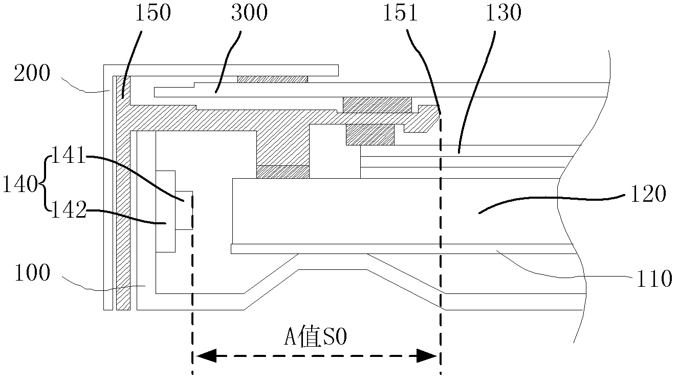
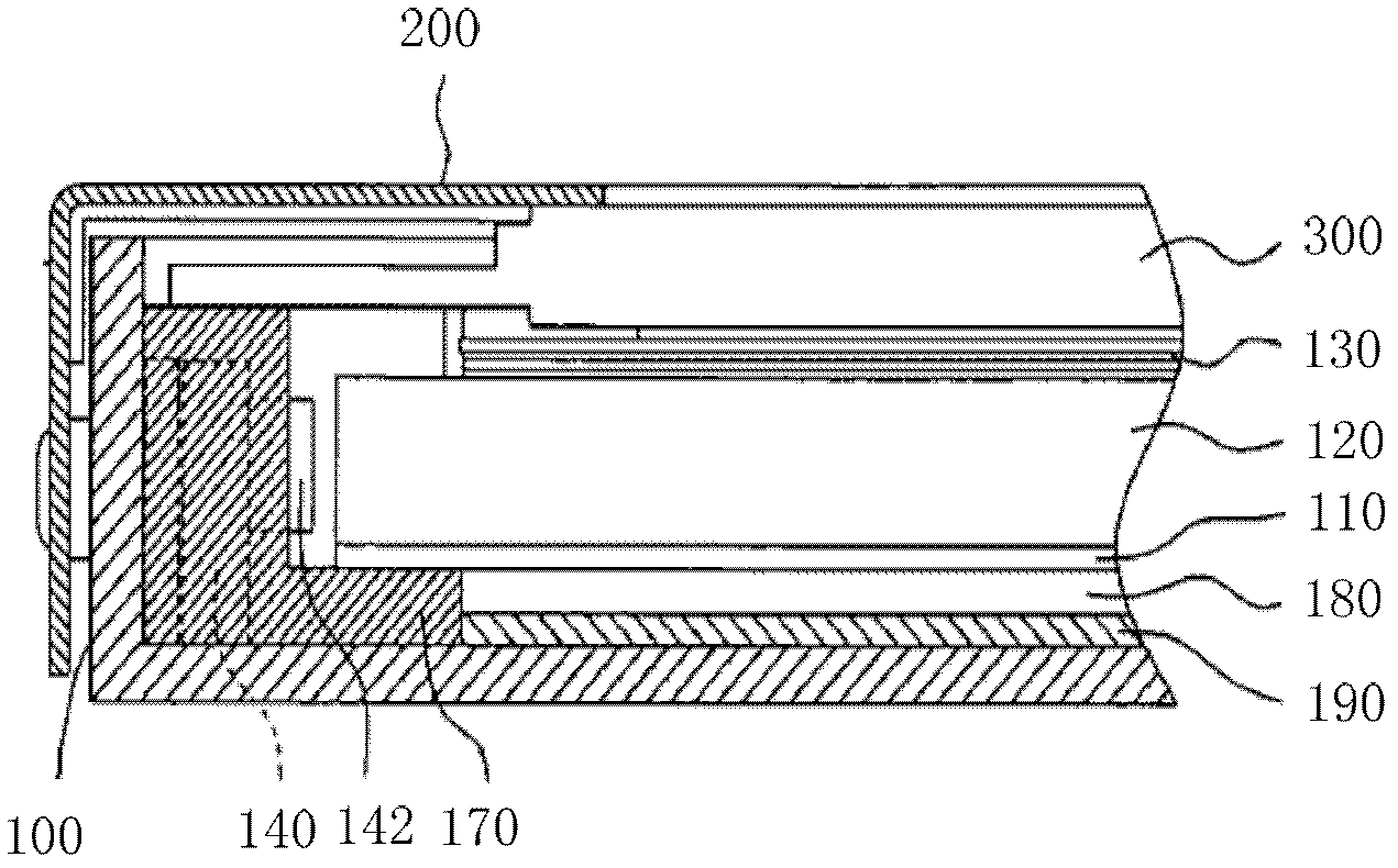
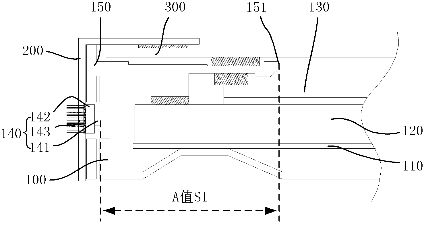
[0034] like image 3 Shown is Embodiment 1 of the present invention. As shown in the figure, the backlight module of the liquid crystal display device includes: a backplane 100, a reflector 110 placed on the backplane 100, placed on the reflector 110 and connected with The light guide plate 120 facing the light bar 140 , the plastic frame 150 and the outer frame 200 arranged outside the back plate 100 and pressed against the light guide plate 120 , the optical film 130 is arranged on the light-emitting surface of the light guide plate 120 , and the liquid crystal panel 300 is composed of Components such as the plastic frame 150 and the outer frame 200 are fixed above the backlight module; wherein, such as Figure 4 As shown, the light bar 140 is arranged on the side wall of the outer frame 200, and the back side of the PCB 142 of the light bar 140 is provided with heat dissipation fins 143, and the heat dissipation fins 143 are in contact with the air outside the outer frame 2...

Embodiment 2

[0039] like Figure 5 Shown is the second embodiment of the present invention, which is different from the first embodiment, such as Image 6 As shown, in this example, the place where the light bar 140 on the outer frame 200 is installed is provided with a boss 210 extending toward the inside of the backlight module. Corresponding to the recess of the backlight module, the purpose of doing so is to facilitate positioning when the backlight module is assembled, and to improve the accuracy and efficiency of assembly. Simultaneously, the thickness setting of the protruding outer frame of the cooling fin 143 is equal to the depth of the boss 210 or less than the depth of the boss 210, so that the cooling fin 143 is completely submerged in the boss 210, ensuring that the cooling fin 143 and the air At the same time, it also prevents the cooling fins 143 from protruding from both sides of the outer frame 200, which will affect the flatness of the outer frame of the liquid crystal ...


PUM


Abstract

The invention discloses a backlight module and a liquid crystal display device comprising the same. The backlight module comprises a light guide plate, a lamp strip and an outer frame, and the lamp strip is optically coupled with the light guide plate, and is mounted onto the outer frame from the inner side. As the lamp strip is mounted on the outer frame of the backlight module, the lamp strip and external air can be in heat exchange to dissipate heat via the outer frame directly. As the lamp strip is directly arranged on the outer frame, a heat conduction path is greatly reduced, heat generated by the lamp strip can be timely dissipated via the outer frame, the temperature in the backlight module is reduced, stability of components in the backlight module is improved, the service lives of the components in the backlight module are prolonged, and the problem that the stability of a liquid crystal panel is affected due to over high temperature is avoided.

Description

technical field [0001] The invention relates to the field of liquid crystal display, and more specifically relates to a backlight module and a liquid crystal display device using the backlight module. Background technique [0002] The backlight module is one of the key components of the liquid crystal display device, which is mainly used to provide sufficient brightness and uniformly distributed light source so that the liquid crystal display device can display images normally. [0003] like figure 1 Shown is a backlight module of a liquid crystal display device, including: a back plate 100, a light bar 140 fixed on the side wall of the back plate 100, a reflector 110 placed on the back plate 100, and a reflector 110 placed between The light guide plate 120 on top and facing the light bar 140, the plastic frame 150 and the outer frame 200 arranged outside the back plate 100 and pressed against the light guide plate 120, the optical film 130 is arranged on the light-emitting...

Claims


Application Information

Patent Timeline
Patent Type & Authority Applications(China)
IPC IPC(8): F21S8/00F21V19/00F21V29/00G02F1/13357F21Y101/02
CPCG02B6/0088F21V29/00G02B6/0093G02B6/009G02F1/133385G02B6/0011F21S2/00G02F2001/133314G02B6/0085G02F1/133608G02F1/133314
Inventor 余亚军李全
Owner SHENZHEN CHINA STAR OPTOELECTRONICS TECH CO LTD
Why Eureka
Try Eureka