Bottom air admission type closed cooling tower

A closed cooling tower and cooling tower technology, applied in water shower coolers, direct contact heat exchangers, heat exchanger types, etc., can solve the problems of small air volume, uneven air distribution, and many fans in the central area. Achieve the effect of saving the cost of structural parts, saving engineering land, and evenly distributing air

Active Publication Date: 2012-08-01
BEIJING LANG BO KE TECH DEV COMPANYLIMITED +1
View PDF5 Cites 22 Cited by
  • Summary
  • Abstract
  • Description
  • Claims
  • Application Information

AI Technical Summary

Problems solved by technology

[0003] 1. The air intake on both sides will cause uneven air distribution on the cross section of the tower body: the air volume near the air inlet is large, and the air volume in the central area is small, which affects the heat exchange efficiency of the cooling tower;
[0004] 2. When the existing countercurrent closed cooling tower handles a large amount of water, the cooling tower composed of a single tube group cannot meet the requirements. Often, multiple grids are connected in parallel to form a row, and then multiple rows form a tower group to meet the requirements of large water flow. ; Since there must be enough distance between each row of towers to meet the requirements of air intake, the design of this tower group occupies a large area
In addition, the tower group is designed with relatively many fans, which is inconvenient to maintain (see figure 2 and image 3 )

Method used


Image

  • Bottom air admission type closed cooling tower
  • Bottom air admission type closed cooling tower
  • Bottom air admission type closed cooling tower

Examples


Embodiment Construction

[0033] Relevant present invention is for reaching above-mentioned purpose of use and effect and the technical means adopted, presents preferred feasible embodiment, and cooperates as shown in the accompanying drawings, detailed description is as follows:

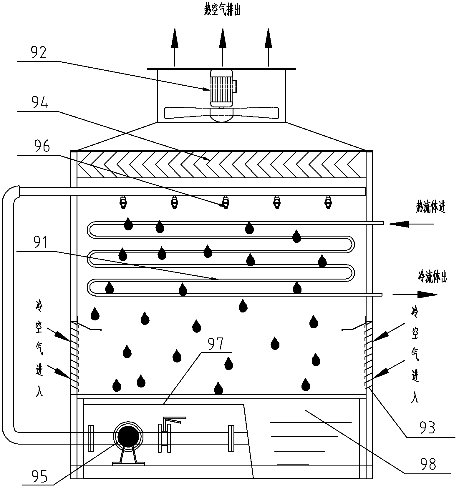
[0034] Such as Figure 4 and Figure 5 Shown, are respectively the sectional view and the side schematic diagram of the closed cooling tower of the present invention bottom air intake; The closed cooling tower of described bottom air intake comprises: blower fan 11, water eliminator 12, spray pipe 13, heat exchange tube Group 14, water guide louvers 15, wind-shielding plate 16, diversion tank 17, water tank 18 and spray pump 19. The fan 11 is arranged on the top of the closed cooling tower shell, the water collector 12 is arranged under the fan 11, the spray pipe 13 is arranged under the water collector 12, and the heat exchange Pipeline 14 is arranged on the below of spray pipe 13, and described water tank 18 is arranged ...


PUM


Abstract

The invention provides a bottom air admission type closed cooling tower, which comprises a fan, a water collector, a spray pipe, a heat exchange tube assembly, a water tank and a spray pump, the fan is arranged on the top in a closed cooling tower shell, the water collector is arranged under the fan, the spray pipe is arranged under the water collector, the heat exchange tube assembly is arrangedunder the spray pipe, the water tank is arranged on the bottom in the closed cooling tower shell, and the spray pump is arranged outside the water tank and respectively communicates with the water tank and the spray pipe; the bottom air admission type closed cooling tower also comprises a plurality of water guide louvers, the water guide louvers are arranged on the bottom of the cooling tower, and moreover, an air inlet is arranged between each two neighboring water guide louvers. When the bottom air admission type closed cooling tower is used, air distribution is more uniform, the heat exchange efficiency is effectively increased, moreover, the arrangement of a group of towers is more benefited, and more project land is saved. When a large-water quantity project is treated, the multi-rowtube assembly arranged under the single fan can effectively solve the problem of large water quantity, more structural part cost is saved, and the bottom air admission type closed cooling tower is convenient to maintain.

Description

technical field [0001] The invention relates to a cooling device, in particular to a bottom-inlet counter-flow closed-type cooling tower, which is suitable for cooling and condensation of circulating cooling water and various low-temperature process media in metallurgy, electric power, chemical industry, oil refining and other industries. Background technique [0002] The existing closed cooling tower in the form of counterflow adopts the air intake form of side air intake, such as figure 1 As shown, one or two fans 92 are set above the heat exchange tube group 91, and the wind enters the tower body through the inlet grilles 93 on both sides, and is drawn out by the fan 91 through the heat exchange tube group 91 and the water eliminator 94. . At the same time, the spray pump 95 presses water into the nozzle 96, and the nozzle 96 sprays the water on the heat exchange tube group 91. During this process, the wind contacts the water, and the heat is taken away by the evaporatio...

Claims


Application Information

Patent Timeline
Patent Type & Authority Applications(China)
IPC IPC(8): F28F25/10F28F25/02
Inventor 魏忠信
Owner BEIJING LANG BO KE TECH DEV COMPANYLIMITED
Why Eureka
Try Eureka