Check patentability & draft patents in minutes with Patsnap Eureka AI!

Inductive position sensor

A measuring device and inductive technology, applied in the direction of measuring device, electric device, special recording/indicating device, etc., can solve problems such as difficulty in adequately shielding external magnetic fields, cumbersomeness, and damage to measurement results.

Active Publication Date: 2015-01-21
罗兰克斯轴承(南京)有限公司
View PDF8 Cites 2 Cited by
  • Summary
  • Abstract
  • Description
  • Claims
  • Application Information

AI Technical Summary

Problems solved by technology

[0005] However, when this path measuring device is used in a motor vehicle, the path measuring device may be affected by magnetic fields formed elsewhere in the vehicle
Adequately shielding external magnetic fields can be difficult and cumbersome in certain installation conditions of the vehicle transmission, but if these external fields are not adequately shielded, there is a risk that the external magnetic field will induce a voltage in the sensor coil and therefore may damage to the measurement results

Method used


Image

  • Inductive position sensor
  • Inductive position sensor
  • Inductive position sensor

Examples


Embodiment Construction

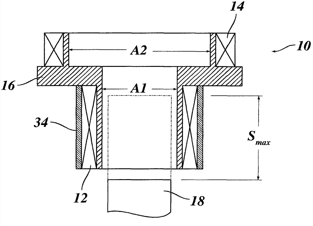
[0018] figure 1 Shown is a coil arrangement 10 with a cylindrical sensor coil 12 , an air-core coil (in this example) and a likewise cylindrical compensating coil 14 . The sensor coil 12 and the compensation coil 14 are coaxially wound on a common carrier 16 made of non-magnetic material with a specific distance from each other. At the end of the sensor 12 opposite the compensating coil 14 is shown the end of a ferromagnetic plunger 18 which moves in the axial direction of the coil arrangement and which penetrates the sensor coil 12 a certain distance S max ,Such as figure 1 shown by the dotted line in . The plunger 18 affects the inductance of the sensor coil 12 such that, by measuring this inductance, the change from the original position of the plunger 18, i.e. figure 1 The solid line shown in , travels the path to the interior of the sensor coil.

[0019] The sensor 12 surrounds a certain annular area A1. The turns of the compensation coil 14 are situated radially out...


PUM


Abstract

#CMT# # / CMT# The device has a measuring plunger that is movable relative to a measuring coil (12). A set of series-connected compensation coils (14) is provided for compensation of interference voltages induced by external magnetic fields. A measuring circuit (20) is provided for measuring inductance of the measuring coil and the compensation coils based on path of the plunger. An electronic evaluation and control unit (28) varies a wiring of the compensation coil based on measured path of the plunger. The measuring coil is enclosed by a sleeve comprising high magnetic permeability material. #CMT#USE : # / CMT# Inductive displacement measuring device for use in a transmission sensor of a motor car. #CMT#ADVANTAGE : # / CMT# The electronic evaluation and control unit varies the wiring of the compensation coil based on measured path of the plunger, thus enhancing measuring accuracy of the measuring device. The compensation coils have a reduced number of turns, thus decreasing inductance of the compensation coils. #CMT#DESCRIPTION OF DRAWINGS : # / CMT# The drawing shows a schematic circuit diagram of an inductive displacement measuring device. 12 : Measuring coil 14 : Series-connected compensation coils 20 : Measuring circuit 28 : Electronic evaluation and control unit 30 : Comparator.

Description

technical field [0001] The invention relates to an inductive path measuring device having: a sensor coil; a plunger movable relative to the sensor coil; a compensation coil arranged coaxially with the sensor coil and connected in series with the sensor coil, to compensate the noise voltage induced in the sensor coil by an external magnetic field; a measuring circuit for measuring the inductance of the sensor coil and compensation coil according to the path of the plunger; and an electronic processing and control unit for measuring the inductance according to the measured inductance Calculate the path the plunger has traveled. [0002] More precisely, the invention relates to a path measuring device in a gear sensor of a motor vehicle. Background technique [0003] WO 2010 / 006781 A1 describes a gear sensor for detecting the current gear of a transmission. In this sensor, a plunger is mechanically connected to a stop member elastically biased with respect to a shift shaft of...

Claims


Application Information

Patent Timeline
Patent Type & Authority Patents(China)
IPC IPC(8): G01D5/22G01D5/20G01B7/02
CPCG01D5/2013G01D3/0365
Inventor R·孟肯米勒
Owner 罗兰克斯轴承(南京)有限公司
Features
  • R&D
  • Intellectual Property
  • Life Sciences
  • Materials
  • Tech Scout
  • Unparalleled Data Quality
  • Higher Quality Content
  • 60% Fewer Hallucinations
Learn More