Dielectric filter, dielectric resonator, cover plate unit and communication equipment
A dielectric resonator and dielectric resonance technology, which is applied to resonators, waveguide devices, electrical components, etc., can solve problems such as poor contact and changes in filter performance indicators, and achieve the effect of reducing dimensional accuracy requirements
- Summary
- Abstract
- Description
- Claims
- Application Information
AI Technical Summary
Problems solved by technology
Method used
Image

Examples
Embodiment 1
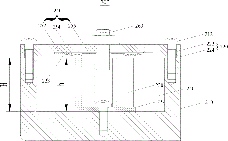
[0033] Embodiment 1, a dielectric resonator. See figure 2 , figure 2 A schematic cross-sectional view of a dielectric resonator 200 and its cover unit 220 according to a preferred embodiment of the present invention is shown. Such as figure 2 As shown, the dielectric resonator 200 includes a cavity 210 , a cover unit 220 and a dielectric resonator column 230 .
[0034] The cover unit 220 covers the cavity 210 to form a resonance cavity 240; the dielectric resonance column 230 is disposed in the resonance cavity 240, and one end of the dielectric resonance column 230 is in contact with the cavity 210, wherein the cover plate The unit 220 includes an upper cover 222 and a lower cover 224, and a spacer 250 disposed between the upper cover 222 and the lower cover 224, through which the spacer 250 provides the lower cover 224 Apply pressure so that the lower cover plate 224 is in close contact with the other end of the dielectric resonant column 230. It should be noted that:...
Embodiment 2
[0055] Embodiment 2, a cover plate unit. Such as Figure 5 shown, shows Figure 4 The schematic diagram of the partial structure of the cover plate unit of the dielectric resonator shown, specifically, Figure 5 A schematic diagram of the lower bottom surface of the upper cover plate of the cover plate unit 420 according to the embodiment of the present invention is shown. Please also see Figure 4 , The cover unit 420 according to the embodiment of the present invention includes an upper cover 422 and a lower cover 424, and the lower cover 424 is relatively thin. The upper cover 422 includes a body 4221 and a protrusion 4222, the protrusion 4222 is in close contact with the lower cover 424; The surface can be formed by stamping. It is easy to understand that the protruding portion 4222 may also be properly disposed on the lower surface of the upper cover plate 422 as an integral protruding block structure or an annular protruding structure. The shape, size and number of...
Embodiment 3
[0056] Embodiment 3, please refer to Figure 6 and Figure 7 , Figure 6 shows a schematic cross-sectional view of a dielectric filter according to a preferred embodiment of the present invention, Figure 7 shown Figure 6 A schematic diagram of the cover unit of the dielectric filter shown.
[0057] From Figure 6 It can be easily seen from the figure that the dielectric filter 500 includes a plurality of the above-mentioned dielectric resonators, and the dielectric filter works through the coupling between the plurality of resonant cavities. Multiple upper cover plates and multiple lower cover plates of multiple dielectric resonators can be integrally formed respectively, forming an integral upper cover plate and an integral lower cover plate, while the cavity is a multi-cavity structure, and the integral lower cover plate and the Each dielectric resonant cylinder is in elastic close contact.
[0058] Figure 8 A schematic cross-sectional view of a dielectric filter 6...
PUM
 Abstract
Description
Claims
Application Information