Device for generating torsional electromagnetic wave and electric power system employing the same

A generation device and power system technology, applied in the direction of electric energy storage system, circuit device, harmonic reduction device, etc., can solve the problems of increasing load power consumption and load power consumption, and achieve excellent performance, low cost, and easy The effect of manufacture

Inactive Publication Date: 2012-08-01
HYUNDAI MOBIS CO LTD
View PDF0 Cites 2 Cited by
  • Summary
  • Abstract
  • Description
  • Claims
  • Application Information

AI Technical Summary

Problems solved by technology

[0008] like figure 1 As shown, because of harmonic components and overvoltage components, AC current ( figure 1 The solid line) and the abnormal sin wave ( figure 1 The dotted line of ) has a considerable difference, so the power consumption of the load increases
[0009] Specifically, the harmonic component is the main factor that increases the power consumption of the load, and the overvoltage component can induce load failure

Method used


Image

  • Device for generating torsional electromagnetic wave and electric power system employing the same
  • Device for generating torsional electromagnetic wave and electric power system employing the same
  • Device for generating torsional electromagnetic wave and electric power system employing the same

Examples


Embodiment Construction

[0039] The specific implementation of the rotary electromagnetic wave generating device of the present invention will be described in detail below with reference to the accompanying drawings.

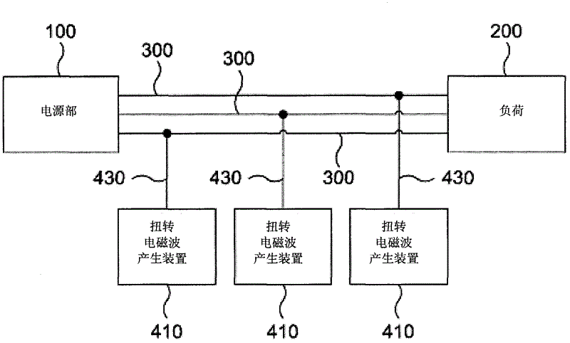
[0040] figure 2 It is a block diagram roughly showing a power system including the rotary electromagnetic wave generating device of the present invention.

[0041] like figure 2 As shown, the power system of the present invention includes a power supply unit 100 and a rotary electromagnetic wave generating device 410 .

[0042] The power supply unit 100 supplies electric power to the load 200 through the electric power line 300 . The power supply part 100 may supply single-phase power or three-phase power to the load 200, but is not limited thereto.

[0043] The power line 300 provides a current flow path connecting the power supply unit 100 and the load 200 .

[0044] The rotating electromagnetic wave generating device 410 adds rotating electromagnetic waves to the power line 300...


PUM


Abstract

The invention relates to a device for generating torsional electromagnetic wave and an electric power system employing the same. In the device and the system, since settings are not related to current amount supplied to the power, voltage, and voltage supply mode, therefore, power use amount of high power electric devices using an induction type engine such as an air conditioner, a refrigerator, etc.

Description

technical field [0001] The present invention relates to a rotary electromagnetic wave generating device and a power system using the device, in particular, to a rotary electromagnetic wave generating device which improves power efficiency by introducing a rotary electromagnetic wave on a power line connecting a power source and a load, and uses the rotary electromagnetic wave generating device The power system of the device. Background technique [0002] The effective electric power P consumed in the load driven by the AC power source can be expressed by calculation formula 1. [0003] [Calculation formula 1] [0004] P=V·I·Φ (where V is the voltage, I is the current, and Φ is the power factor) [0005] According to the calculation formula 1, reducing the voltage or current can reduce the power consumed in the load. [0006] However, since there is a rated voltage for normally driving the load, the voltage supplied to the load cannot be reduced. Accordingly, in order to ...

Claims


Application Information

Patent Timeline
Patent Type & Authority Applications(China)
IPC IPC(8): H02J3/01H02H9/04
CPCH02J3/01Y02E40/40H02J15/00
Inventor 卢暎雨朴昌辉朴洙用卞泰善
Owner HYUNDAI MOBIS CO LTD
Why Eureka
Try Eureka