Transmission system and powered device

A transmission system and transmission system technology, which is applied in the field of transmission system and power receiving device, can solve the problems of transmission efficiency reduction, display miniaturization, etc., and achieve the effect of expanding the area

Inactive Publication Date: 2012-08-01
KYUSHU UNIV +1
View PDF1 Cites 0 Cited by
  • Summary
  • Abstract
  • Description
  • Claims
  • Application Information

AI Technical Summary

Problems solved by technology

However, if the size of the power receiving electrode is reduced, there is a problem that the transmission efficiency will decrease
In addition, the miniaturization of the pixel electrode causes the problem that the display part has to be miniaturized

Method used


Image

  • Transmission system and powered device
  • Transmission system and powered device
  • Transmission system and powered device

Examples


Embodiment

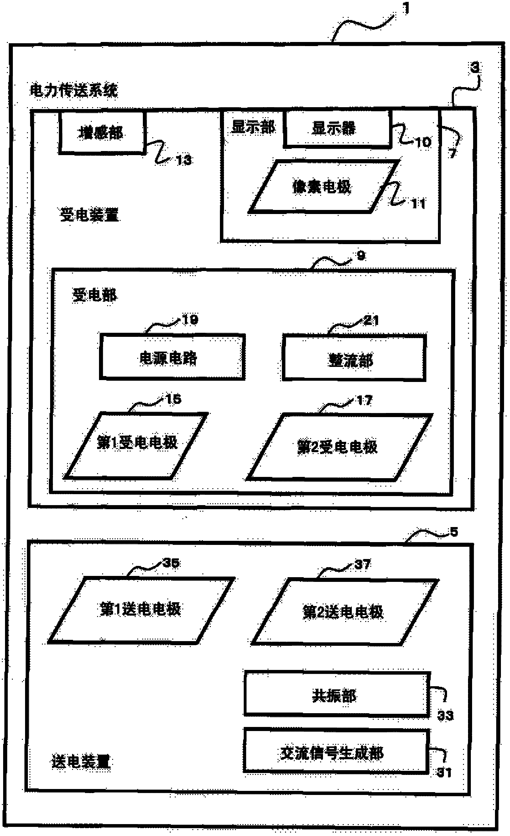
[0037] First, refer to figure 1 , illustrating the delivery system of the present invention. figure 1 It is a block diagram of the transmission system 1 which concerns on embodiment of this invention.

[0038] Transmission system 1 (an example of "transmission system" in the technical solution of this application) includes a power receiving device 3 (an example of "electronic paper device" or "power receiving device" in the technical solution of this application) and a power transmission device 5 (an example of a "power receiving device" in this technical solution). An example of the "power transmission device" in the technical solution of the application). The power receiving device 3 is a thin power receiving device including a display unit, and receives electrical signals from the power transmitting device 5 through two power receiving electrodes in a non-contact manner. The power transmitting device 5 transmits an electric signal to the power receiving device 3 in a non-...


PUM


Abstract

Provided is a transmission system, which is capable of transmitting electric signals with high efficiency in a non-contact manner by means of capacitive coupling to a thin powered device where a display part is charged. The transmission system has a power supply device for electric signal transmission, and an electronic paper device which receives the electric signal in a non-contact manner by at least two powered electrodes. The electronic paper device has a display part for displaying images. The display part has a pixel electrode for charging the display part. In the electronic paper device, there is provided a pixel electrode region, which is formed in the way that the pixel electrode surface is parallely moved along a direction perpendicular to the pixel electrode surface which has the maximum area, within a surface which exists under the pixel-electrode flattened state. The first powered electrode, as one of the powered electrodes, receives the electric signal from a region beyond the pixel electrode region.

Description

technical field [0001] The present invention relates to a transmission system and a power receiving device, and particularly relates to a power transmitting device that transmits an electric signal (including electric power. Also, a signal that superimposes an information signal on the electric power. The same applies hereinafter.) and a power receiving device that receives the electric signal. A transmission system that transmits electrical signals to each other in a non-contact manner. Background technique [0002] Conventionally, transmission systems have been developed that transmit electrical signals from a power transmitting device to a power receiving device in a non-contact manner. Among them, the method of transmitting electrical signals using electromagnetic induction requires precise adjustment of the positional relationship between the power transmitting side and the power receiving side. Therefore, as a means of alleviating the constraints on the positional rel...

Claims


Application Information

Patent Timeline
IPC IPC(8): H02N1/08G06K19/07H04B5/02
CPCY02D30/70
Inventor 服部励治石西洋平川刚渡边明彦
Owner KYUSHU UNIV
Why Eureka
Try Eureka