Position-sensor-free control method applicable to middle-high-speed switch reluctance motors

A technology of switched reluctance motor and control method, which is applied in the direction of electronically commutated motor control, control system, electronic commutator, etc., can solve the problems of reducing the detection accuracy and inability to accurately estimate the rotor position, so as to improve the accuracy, Easy-to-implement, simple-to-control effects

Inactive Publication Date: 2012-08-01
NANJING UNIV OF AERONAUTICS & ASTRONAUTICS
View PDF2 Cites 20 Cited by
  • Summary
  • Abstract
  • Description
  • Claims
  • Application Information

AI Technical Summary

Problems solved by technology

This method only needs a small amount of static measurement, and the control is simple and easy to implement, but it cannot accurately estimate the rotor position, which reduces the detection accuracy

Method used


Image

  • Position-sensor-free control method applicable to middle-high-speed switch reluctance motors
  • Position-sensor-free control method applicable to middle-high-speed switch reluctance motors
  • Position-sensor-free control method applicable to middle-high-speed switch reluctance motors

Examples


Embodiment Construction

[0024] The technical solutions of the present invention will be described in detail below in conjunction with the accompanying drawings.

[0025] The present invention provides a position sensorless control method suitable for medium and high speed switched reluctance motors, comprising the following steps:

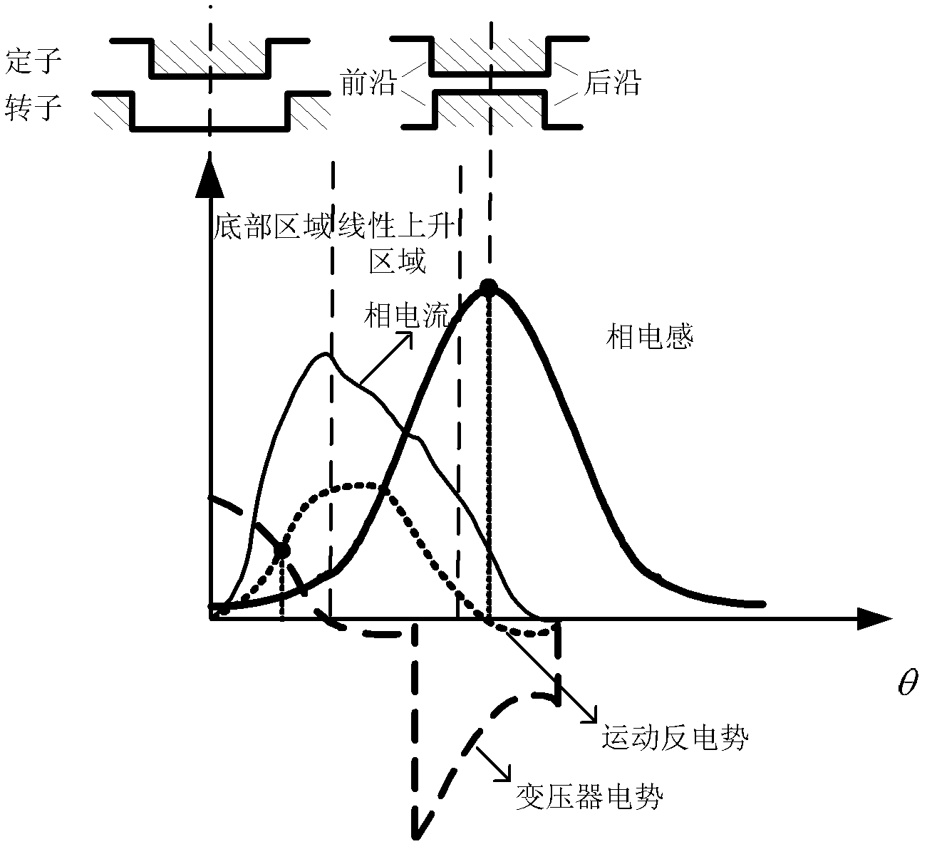
[0026] (1) In the single pulse width operation mode, determine the intersection point of the motion back EMF curve and the transformer potential curve in the bottom area before the inductance linearly rises;
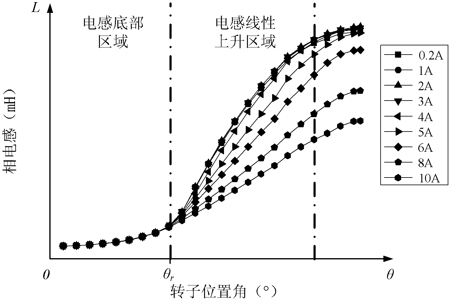
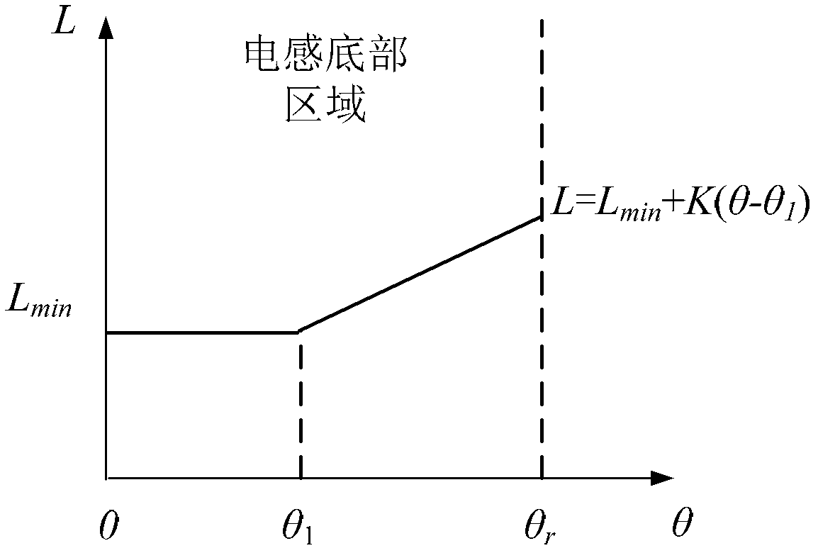
[0027] The area of ​​the switched reluctance motor inductance curve from the position where the stator tooth axis coincides with the rotor slot axis to the position where the stator tooth trailing edge begins to coincide with the rotor tooth leading edge is the bottom area before the inductance rises linearly. The inductance in this area hardly changes with the load current. Therefore, the present invention uses the uniqueness of the inductance curve to realize the ...


PUM


Abstract

The invention discloses a position-sensor-free control method applicable to middle-high-speed switch reluctance motors, which includes the following steps: (1) in a single-pulse-width running mode, determining an intersecting point of a moving counter electromotive force curve and a transformer potential curve in a bottom area before an inductance linearly raises up; (2) fitting an inductance curve in the bottom area before the inductance linearly raises up by utilizing an inductance model, and solving a theoretical value of a rotor position corresponding to the intersecting point of the moving counter electromotive force curve and the transformer potential curve determined in the step (1); and (3) calculating the real-time rotating speed by the aid of the intersecting point determined in the step (1), and estimating a random position according to the specific rotor position and the real-time rotating speed to realize the normal operation of the motor and the adjustable control to the switch-on angle and the switch-off angle. The position-sensor-free control method applicable to the middle-high-speed switch reluctance motors is simple and easy to realize, capable of estimating the rotor positions in equilibration and non-equilibration conditions, and capable of realizing the adjustable control to the switch-on angle and the switch-off angle.

Description

technical field [0001] The invention belongs to the field of sensorless control of switched reluctance motors, in particular to a position sensorless control method of switched reluctance motors suitable for medium and high speeds. Background technique [0002] Switched reluctance motor has the advantages of simple structure, reliable operation, good fault tolerance, low cost and flexible control, so it has attracted the attention of academia. At present, switched reluctance motors have been widely used in aviation industry, locomotive traction, mine excavation and household appliances, etc., showing their potential advantages and good market prospects. [0003] For the switched reluctance motor drive system, it is necessary to obtain the position information of the rotor in real time and accurately to ensure the reliable operation and high-performance control of the motor. At present, external photoelectric or magnetic sensitive position detectors are generally used. The ...

Claims


Application Information

Patent Timeline
IPC IPC(8): H02P6/18H02P6/182
Inventor 周竟成王晓琳邓智泉蔡骏
Owner NANJING UNIV OF AERONAUTICS & ASTRONAUTICS
Why Eureka
Try Eureka