Real-time calibration method and real-time calibration device for multi-channel transmitter radio frequency response

A calibration method and transmitter technology, applied in transmitter monitoring, space transmit diversity, diversity/multi-antenna systems, etc., can solve problems such as system performance deterioration, calibration of multi-channel transmitters, data post-processing, channel estimation effects, etc. Achieve the effect of convenient calibration

Inactive Publication Date: 2012-08-01
TSINGHUA UNIV
View PDF4 Cites 16 Cited by
  • Summary
  • Abstract
  • Description
  • Claims
  • Application Information

AI Technical Summary

Problems solved by technology

The response of the transmitting radio frequency channel will change with time, and the parameters such as the gain and phase of the amplifier and other devices will change with the change of factors such as temperature. As a result, in a multi-channel transceiver, the response of each radio frequency channel is different. The difference between them will lead to the deterioration of system performance
For example, if the data of each channel to be transmitted is orthogonal to each other, due to the differences between the radio frequency channels, after passing through the multi-channel transmitter, the data of each channel is no longer orthogonal, which will affect data post-processing, channel estimation, etc.
[0005] In the prior art, a calibration method is to connect the multi-channel transmitter and the calibra

Method used


Image

  • Real-time calibration method and real-time calibration device for multi-channel transmitter radio frequency response
  • Real-time calibration method and real-time calibration device for multi-channel transmitter radio frequency response
  • Real-time calibration method and real-time calibration device for multi-channel transmitter radio frequency response

Examples


Embodiment Construction

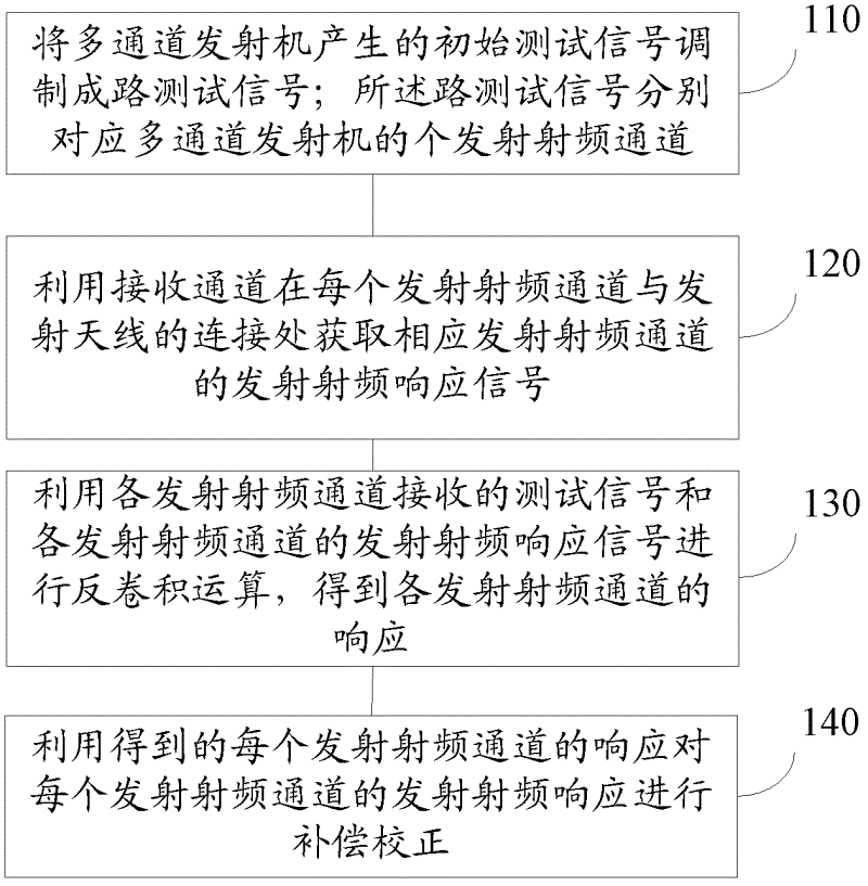
[0037] In order to make the above objects, features and advantages of the present application more obvious and comprehensible, the present application will be further described in detail below in conjunction with the accompanying drawings and specific implementation methods.

[0038] In practice, each transmit RF channel i of a multi-channel transmitter responds x i will produce a response y when i , the RF response signal generated by the transmitting RF channel is z i , but normally the response y of each transmit RF channel i i It is not known, and will change with the application environment, such as time changes, the gain, phase and other parameters of amplifiers and other devices will change with factors such as temperature, and the response y of the transmitting radio frequency channel i i There will be changes, if the y is not measured in time i value, and then compensate and correct the receiving RF response of each transmitting RF channel, which will have an impac...


PUM


Abstract

The invention provides a real-time calibration method and a real-time calibration device for multi-channel transmitter radio frequency response, which relate to the technical field of wireless communication. The method includes that initial testing signals generated by a multi-channel transmitter are modulated into m-branch testing signals; the m-branch testing signals correspond to m transmitting radio frequency channels of the multi-channel transmitter respectively; transmitting radio frequency response signals of corresponding transmitting radio frequency channels are obtained at each connection position of each transmitting radio frequency channel and a transmitting antenna by using receiving channels; testing signals received by each transmitting radio frequency channel and transmitting radio frequency response signals of each transmitting radio frequency channel are used to conduct deconvolution operation and obtain response of each transmitting radio frequency channel; and compensation calibration is conducted on the transmitting radio frequency response of each transmitting radio frequency channel by using the obtained response of each transmitting radio frequency channel. The real-time calibration method and the real-time calibration device can achieve obtaining of the response of each transmitting radio frequency channel only in the multi-channel transmitter and can calibrate the transmitting radio frequency response in various application situations in real time and conveniently during actual application.

Description

technical field [0001] The present application relates to the technical field of wireless communication, in particular to a method and device for real-time calibration of radio frequency response of a multi-channel transmitter. Background technique [0002] With the development of modern communication technology, the test requirements for its equipment are getting higher and higher, not only the reliability of the test but also the efficiency of the test are required. [0003] In the development of future communication, multiple-input multiple-output antenna technology (Multiple-Input Multiple-Output, MIMO) and other technologies will inevitably be used in future wireless communication systems, which can improve the information transmission rate. In order to make good use of the advantages brought by MIMO More channel information will inevitably introduce multiple radio frequency channels. [0004] The calibration of the transmitting radio frequency channel is very importan...

Claims


Application Information

Patent Timeline
IPC IPC(8): H04B17/00H04B7/06H04B17/11
Inventor 张焱周跃键赵熠飞肖立民栾凤宇陈翔周世东
Owner TSINGHUA UNIV
Why Eureka
Try Eureka