
Controller shell for electric vehicle

A technology for electric vehicle controllers and casings, which is applied in the direction of metal casings, cooling/ventilation/heating transformation, etc., and can solve the problem of poor performance of controller circuit board components, damage of controller circuit board components, failure to timely and fully problems such as heat dissipation, to achieve the effect of long-term stable work, good heat dissipation, and strong online monitoring

Inactive Publication Date: 2012-08-01
唐河阳
View PDF4 Cites 9 Cited by
  • Summary
  • Abstract
  • Description
  • Claims
  • Application Information

AI Technical Summary

Problems solved by technology

[0002] At present, most of the small and medium power controllers used in electric vehicles in the market adopt the natural heat dissipation method of the shell. This method can easily lead to high temperature inside the controller due to the inability to dissipate heat in a timely and sufficient manner, resulting in poor performance and shortened life of controller circuit board components.
Some high-power controllers adopt the traditional air-cooled heat dissipation method, which directly blows and cools the circuit board components of the controller through an external fan. Since the internal and external environments cannot be isolated, the circuit board components of the controller are easily polluted by dust and die prematurely. Damaged and unable to achieve water and moisture resistance

Method used


Image

  • Controller shell for electric vehicle
  • Controller shell for electric vehicle
  • Controller shell for electric vehicle

Examples


Embodiment 1

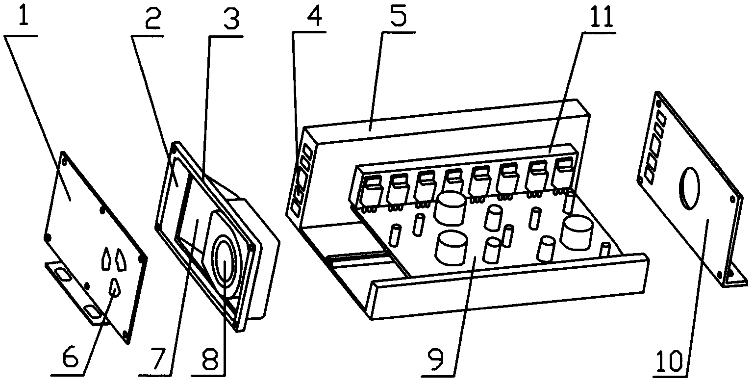
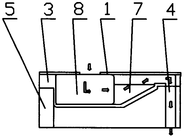
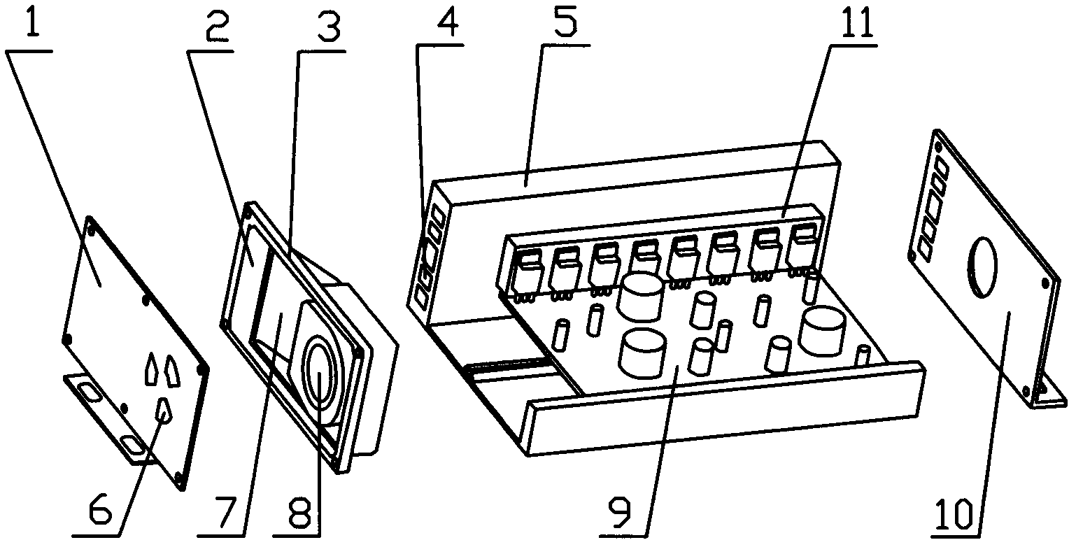
[0018] Such as figure 1 , figure 2 Shown, a kind of electric vehicle controller shell, its main body is aluminum shell 5, and aluminum shell 5 is the cylinder body that cross section is square, and the two ends of aluminum shell 5 are respectively made of front fender 10, rear fender The board 1 is closed, the rear baffle 1 is equipped with a fan 8, the circuit board 9 is fixedly connected to the inner wall of the aluminum housing 5, and a heat dissipation air duct 4 is opened on the side wall of the aluminum housing 5 along the length direction of the aluminum housing. , the heat dissipation air duct 4 is five channels arranged vertically, each channel is horizontal and parallel to each other, the heat dissipation air duct 4 runs through the side wall of the aluminum shell; There is a groove on the inner surface, and the heat dissipation aluminum strip 11 is fixed in the groove. The CMOS power tube is connected to the heat dissipation aluminum bar 11 . An air flow steerin...


PUM


Abstract

The invention discloses a controller shell for an electric vehicle. A main body of the controller shell is an aluminum shell; two ends of the aluminum shell are respectively sealed by a front baffle plate and a back baffle plate; a blower is arranged on the front baffle plate or the back baffle plate; a circuit board is fixedly connected to an inner wall of the aluminum shell; heat radiation air channels are formed on a side wall of the aluminum shell along the length direction of the aluminum shell; the inner side surface of the side wall, which is provided with the heat radiation air channels, of the aluminum shell is connected with heat radiation aluminum strips; a wind current turning structural member is arranged between the back baffle plate and the aluminum shell; one side of the wind current turning structural member, is provided with the blower, and the other side of the wind current turning structural member is provided with air outlet holes; and the air outlet holes are opposite to the heat radiation air channels. The external cold air is absorbed by the blower, and the heat radiation aluminum strips which are internally embedded in the shell are subjected to forced cooling heat radiation through the heat radiation air channels on the inner side of the shell, so that the problems of incapability of dissipating heat from the shell in time due to temperature rise in a natural heat radiation way and incapability of isolating internal and external environments in the conventional air cooling heat radiation way are solved, and good waterproof and moistureproof functions are realized.

Description

technical field [0001] The invention relates to a housing with heat dissipation function of a controller used on an electric vehicle. Background technique [0002] At present, most of the small and medium power controllers used in electric vehicles in the market adopt the natural heat dissipation method of the shell. Since this method cannot dissipate heat in a timely and sufficient manner, it can easily lead to high temperature inside the controller, resulting in poor performance and shortened life of controller circuit board components. Some high-power controllers adopt the traditional air-cooled heat dissipation method, which directly blows and cools the circuit board components of the controller through an external fan. Since the internal and external environments cannot be isolated, the circuit board components of the controller are easily polluted by dust and die prematurely. damaged, and cannot be water and moisture resistant. Contents of the invention [0003] The...

Claims


Application Information

Patent Timeline
Patent Type & Authority Applications(China)
IPC IPC(8): H05K5/04H05K7/20
Inventor 唐河阳任永唐俊涛
Owner 唐河阳
Learn More