
Transition section-free monopile offshore wind turbine foundation structure

A technology for offshore wind turbines and infrastructure, applied in infrastructure engineering, construction, etc., can solve problems such as hidden safety hazards, and achieve the effects of firm connection, improved durability, and simple and fast leveling methods.

Active Publication Date: 2014-11-12
POWERCHINA HUADONG ENG COPORATION LTD
View PDF8 Cites 0 Cited by
  • Summary
  • Abstract
  • Description
  • Claims
  • Application Information

AI Technical Summary

Problems solved by technology

[0006] In recent years, it has been found that some foreign offshore wind turbines have gaps and vertical displacements between the single pile foundation grouting material and the transition section, which poses certain safety hazards

Method used


Image

  • Transition section-free monopile offshore wind turbine foundation structure
  • Transition section-free monopile offshore wind turbine foundation structure
  • Transition section-free monopile offshore wind turbine foundation structure

Examples


Embodiment 1

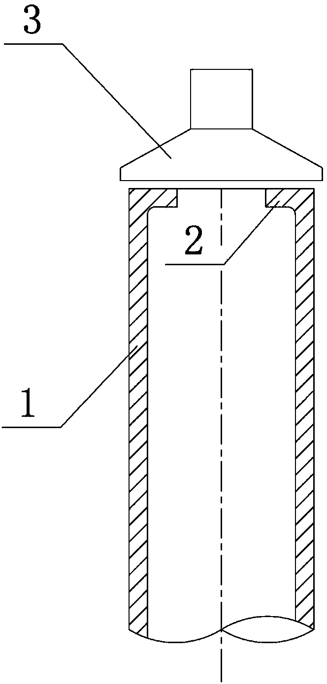
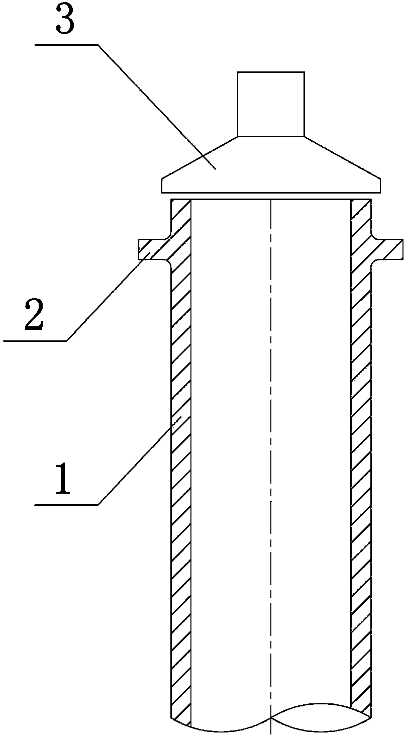
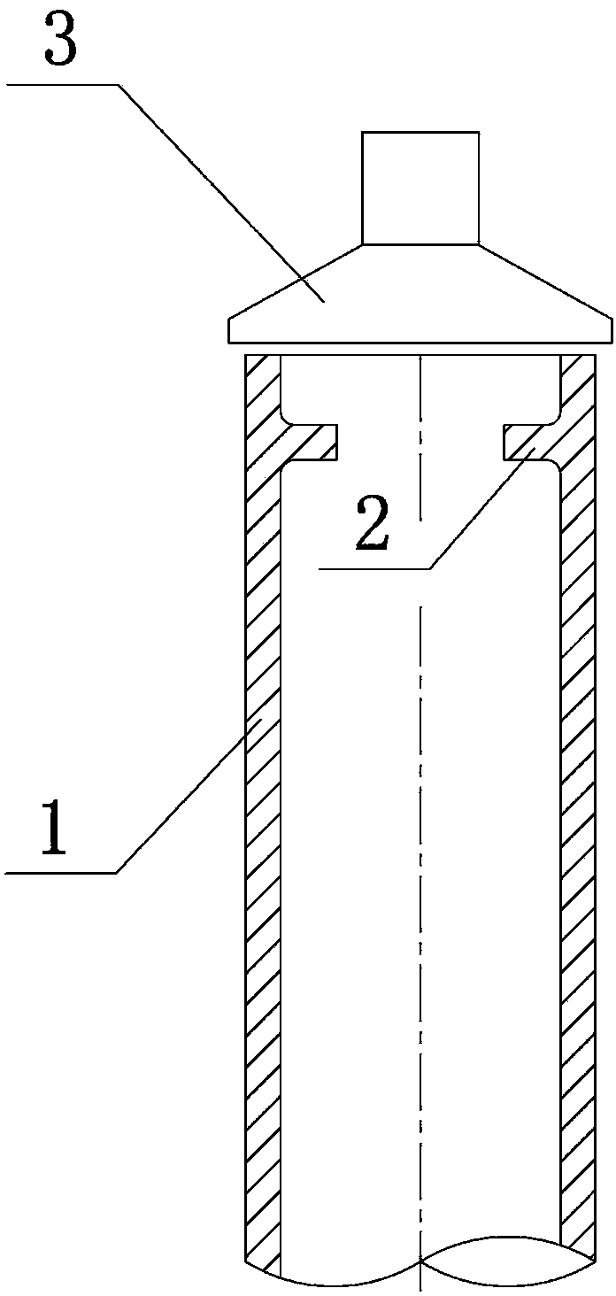
[0024] Embodiment 1: as Image 6 As shown, this embodiment includes a super-large-diameter steel pipe pile 1 driven into the seabed to a certain depth, the pile diameter is 4000mm~6500mm, the top of the pile is welded to the foundation top flange 2 in the factory, and the foundation top flange is arranged on the steel pipe pile 1 and the upper surface of the flange is flush with the top surface of the steel pipe pile 1. This example also includes a fan bottom section tower 13 connected to the upper end of the steel pipe pile 1 , and a bottom section tower flange 12 is provided at the bottom of the fan bottom section tower 13 . A double gasket leveling structure is set between the bottom tower flange 12 and the foundation top flange 2, and the two flanges are tightly connected by bolts 10 and nuts 11.

[0025] Among them, the double gasket leveling structure includes two gaskets I9 with exactly the same specifications. The gasket I is an annular gasket with uniform height chan...

Embodiment 2

[0032] Embodiment 2: The basic structure of this embodiment is the same as that of Embodiment 1, the only difference is that a three-gasket adjustment structure is set between the top flange 2 of the foundation and the tower flange 12 of the bottom section (such as Figure 8 As shown), the structure is composed of three different specifications of circular gaskets II14 with uniform variable height and equal diameter, stacked up and down, and the height of gasket II14 varies from 20 to 80 mm. The outer diameter of the gasket Ⅱ14 is the same as that of the top flange 2 of the foundation, and a circle of bolt holes is uniformly arranged on each gasket Ⅱ14 along the circumference, and the number and position of the bolt holes are the same as those of the top flange 2 of the foundation and the tower flange of the bottom section. 12 are all corresponding; the adjustment level of gasket II14 of three specifications is 1‰, 2‰ and 5‰ respectively. Generally, 1~3 ring gaskets II14 of di...

Embodiment 3

[0033] Embodiment 3: as Figure 9As shown, the top of the steel pipe pile 1 is the top flange 2 of the foundation. Due to the piling accuracy, the steel pipe pile 1 will be inclined, resulting in an inclination of the upper surface of the flange. Section tower tube 13, make tower tube verticality meet requirement. Bolts 10 and nuts 11 are used to tightly connect the bottom section tower flange 12 and the foundation top flange 2 .


PUM


Abstract

The invention relates to a transition section-free monopole offshore wind turbine foundation structure, and aims to provide a transition section-free monopole offshore wind turbine foundation structure, which is simple in structure, convenient to construct and high in cost performance. A transition section is eliminated, so that engineering cost is saved, firm connection is ensured, and the failure risk of a grouting compound is eliminated. The technical scheme of the invention is as follows: the transition section-free monopole offshore wind turbine foundation structure is provided with a monopile steel pipe pile and a wind turbine bottom section tower connected with the steel pipe pile, and is characterized in that a foundation top flange is arranged at the top of the steel pipe pile; a bottom section tower flange is arranged at the bottom of the wind turbine bottom section tower; a leveling mechanism is arranged between the two flanges; and the two flanges are connected through bolts and nuts. The transition section-free monopole offshore wind turbine foundation structure is applied to the offshore wind power generation industry.

Description

technical field [0001] The invention relates to an offshore wind turbine foundation structure, in particular to a single-pile offshore wind turbine foundation structure without a transition section. Suitable for offshore wind power industry. Background technique [0002] With the maturity of wind power generation technology, the way of increasing energy supply by relying on wind power generation is more and more favored by countries all over the world. At present, more than 70 countries and regions in the world are developing wind power to varying degrees, and have formulated a series of encouraging policies to promote the development of the wind power industry. The global wind power industry is growing rapidly at a rate of about 25% per year. [0003] The vast ocean has long attracted people's attention because of its abundant and stable wind energy resources. However, due to the difficulty of offshore construction operations, the complex and changeable marine environmen...

Claims


Application Information

Patent Timeline
Patent Type & Authority Patents(China)
IPC IPC(8): E02D27/44E02D27/42E02D27/52
Inventor 姜贞强孙杏建郇彩云赵朝志高宏飚张乐平葛国林郑永明朱彬彬罗金平李炜吕娜
Owner POWERCHINA HUADONG ENG COPORATION LTD
Learn More