Supercharge Your Innovation With Domain-Expert AI Agents!

Cursor control device and method

A technology of cursor control and mouse cursor, which is applied to the input/output process of instruments, electrical digital data processing, and data processing, etc. It can solve the problems of uneconomical use, ugly scratches on the surface of the touch screen, affecting the display effect, etc., and achieve convenient operation. Effect

Active Publication Date: 2012-08-08
SHENZHEN INST OF ADVANCED TECH CHINESE ACAD OF SCI
View PDF2 Cites 9 Cited by
  • Summary
  • Abstract
  • Description
  • Claims
  • Application Information

AI Technical Summary

Problems solved by technology

The equipment using the laser method is generally relatively large in size, and because the laser generator needs to consume a lot of energy, it is not economical to use in daily life.
[0003] The traditional mouse, touch screen and other devices have a short range of action, which cannot meet some medium-distance input requirements, such as teachers' lectures, slide presentations, etc.
The mouse needs to be in contact with the substrate, and the input is made through the friction between the rolling ball and the substrate or the photoelectricity according to the change of the substrate; will be useless
[0004] Traditional input devices mostly rely on mechanical pressing, friction, etc. to complete signal collection; these methods are inevitably accompanied by mechanical wear, which greatly shortens the service life of the product
At the same time, the traditional resistive touch screen often requires a large force input to obtain a more accurate positioning, which often leaves unsightly scratches on the surface of the touch screen, which not only affects the display effect, but also causes the inaccuracy of the input device itself

Method used


Image

  • Cursor control device and method
  • Cursor control device and method
  • Cursor control device and method

Examples


Embodiment Construction

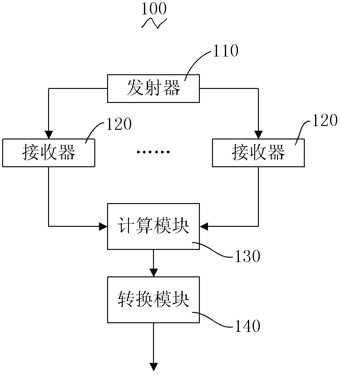
[0037] In order to solve the problems of wear and inconvenience caused by traditional mouse and touch screen operations, a cursor control device and method without contact operation are proposed.

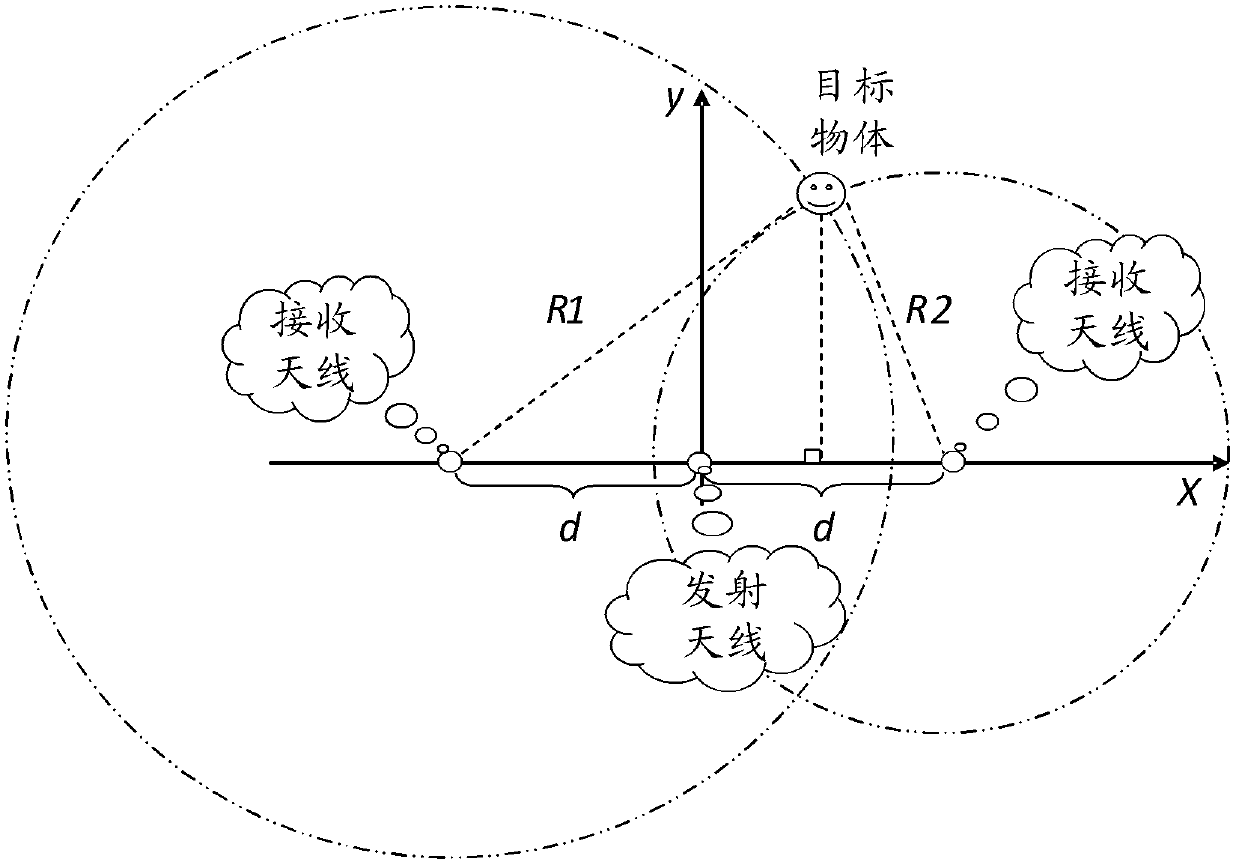
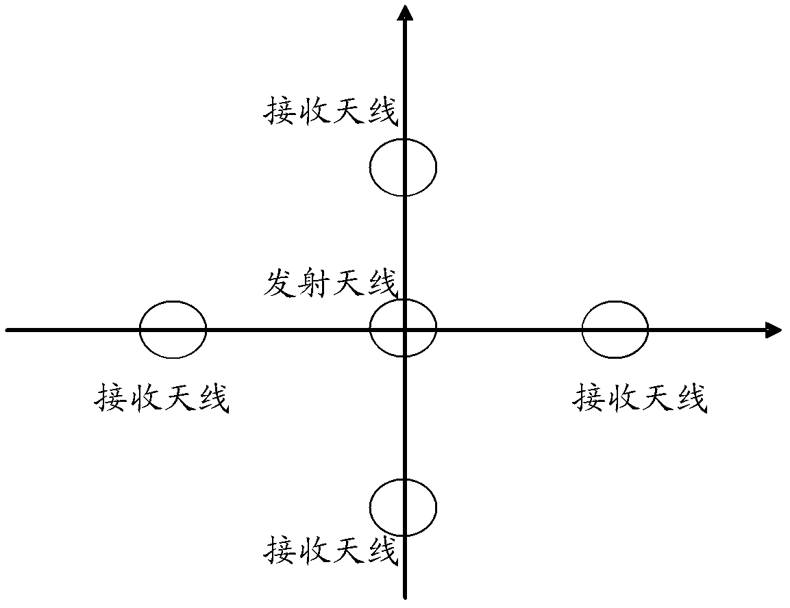
[0038] The ultra-wideband (UltrawideBand, UWB) radar positioning technology is the basis of the present invention. The reason why the ultra-wideband radar is selected here is mainly considering that the size of the sensitive area required by the system is different in different usage scenarios. For conventional radar, its bandwidth is narrow, and the relationship between the resolution and bandwidth of the radar is roughly as follows: In the formula: B is the signal bandwidth, and c is the propagation speed of the radar signal in the air (approximately equal to the speed of light). It can be seen that the wider the signal bandwidth, the higher the resolution of the radar. For short-range (within 1 meter) application scenarios, the flight time of radio waves: To resolve multiple...


PUM


Abstract

The invention relates to a cursor control device which comprises a transmitter, receivers, a computation module and a conversion module. The transmitter is used for transmitting an ultra wide band radar signal; at least two receivers are provided, are distributed at the positions at equal distances to the transmitter and are used for receiving the ultra wide band radar signal; the computation module is used for computing position coordinates of a target object according to difference of time that different receivers receive the ultra wide band radar signal and the distance between the transmitter and the receivers; and the conversion module is used for changing and converting the position coordinates of the target object into a movement and click control signal of a mouse cursor. The invention also provides a corresponding cursor control method. Through the adoption of the cursor control device and the cursor control method, under the condition that people have lessons in a classroom or the distance between people and a machine is long, the transmitter and the receivers can be placed at proper positions so as to realize non-contact control on the movement and click operation of the mouse cursor; and the cursor control device not only cannot be abraded, but also is convenient to operate.

Description

【Technical field】 [0001] The present invention relates to the technical field of electronic product control, in particular to a control device and method for controlling a cursor similar to a mouse. 【Background technique】 [0002] The rapid development of computer technology, the mouse can be described as a major contribution. With the popularization of embedded computing and ubiquitous computing concepts, touch screen technology gradually replaces the mouse on mobile terminals and becomes the main human-computer interaction window. Both the mouse and the touch screen require direct contact with human hands, and at the same time, they are accompanied by mechanical wear and consumption to varying degrees, so that both of them become consumables and have to be replaced frequently, resulting in a waste of resources. At the same time, when teachers give lectures or lecture on slides, people need more interactive input methods, which cannot be achieved by ordinary mice and touch...

Claims


Application Information

Patent Timeline
IPC IPC(8): G06F3/033
Inventor 胡波平李烨
Owner SHENZHEN INST OF ADVANCED TECH CHINESE ACAD OF SCI
Features
  • R&D
  • Intellectual Property
  • Life Sciences
  • Materials
  • Tech Scout
  • Unparalleled Data Quality
  • Higher Quality Content
  • 60% Fewer Hallucinations
Learn More