
Splitting spinning mold with retainer stages and determination method for retainer stages

A technology of stopping and moving tables, applied in the direction of forming tools, manufacturing tools, metal processing equipment, etc., can solve the problems of workpiece sliding and eccentricity, affecting spinning processing, stuck and unable to rotate, etc., to prevent sliding and eccentricity, prevent Eccentric effect

Active Publication Date: 2012-08-15
NORTHWESTERN POLYTECHNICAL UNIV
View PDF8 Cites 1 Cited by
  • Summary
  • Abstract
  • Description
  • Claims
  • Application Information

AI Technical Summary

Problems solved by technology

[0004] In order to overcome the friction existing in the prior art, it is difficult to continue to drive the workpiece and the driven mandrel to rotate synchronously with the main shaft, and cause the workpiece to slide and eccentrically, or even get stuck and cannot rotate, thereby affecting the normal spinning process. The invention proposes a fractal spinning die with a stopper and a method for determining the stopper

Method used


Image

  • Splitting spinning mold with retainer stages and determination method for retainer stages
  • Splitting spinning mold with retainer stages and determination method for retainer stages
  • Splitting spinning mold with retainer stages and determination method for retainer stages

Examples


Embodiment Construction

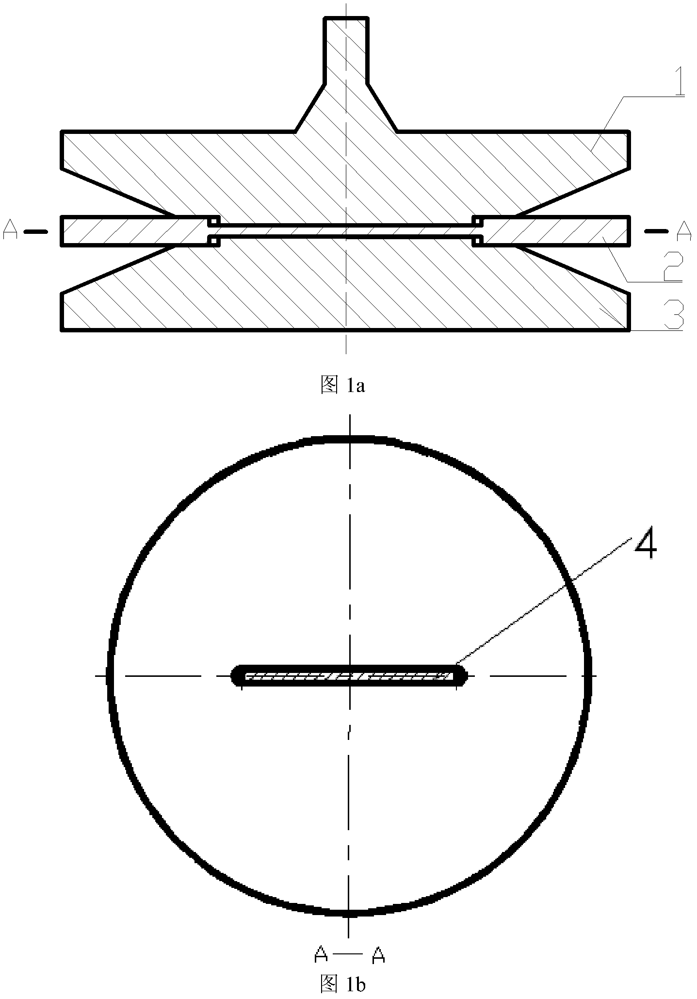
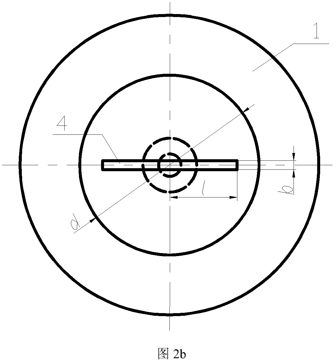
[0041] This embodiment is a mold for integral wheel hub fractal spinning, and the wheel hub fractal spinning mold is used for forming a wheel hub with a mounting surface diameter of 120mm. In this embodiment, a circular LF21M aluminum alloy is used as the blank material, and the diameter of the blank is 200 mm, and the thickness of the blank is t 0 = 10mm; Since the diameter of the mounting surface of the formed hub is 120mm, the diameter d of the small end of the driving mandrel and the driven mandrel is both 120mm.

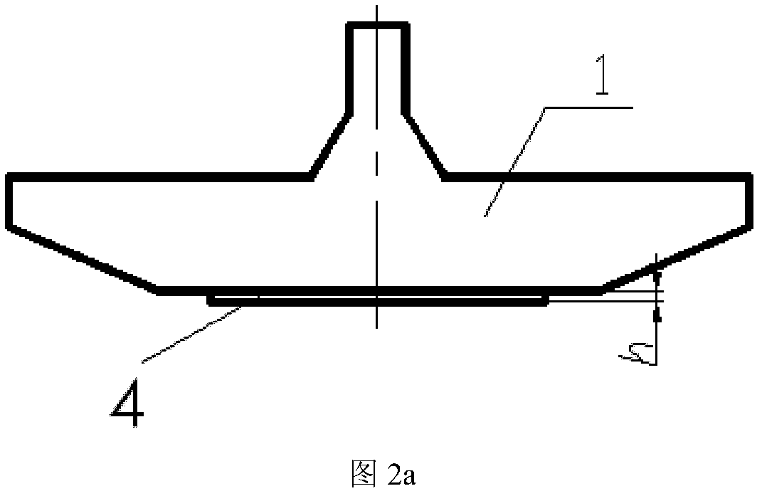
[0042]This embodiment includes a driving mandrel 1 and a driven mandrel 3 . The active mandrel 1 is a revolving body with an inverted trapezoidal longitudinal section, and the peripheral surface of the active mandrel 1 is the forming surface of the hub. In the center of the large end face of the active mandrel 1 there is a connecting plunger fixedly connected to the machine tool spindle, and in the center of the small end face of the active mandrel 1 there is a...


PUM

PropertyMeasurementUnit
tensile strengthaaaaaaaaaa
shear strengthaaaaaaaaaa

Abstract

The invention discloses a splitting spinning mold with retainer stages and a determination method for the retainer stages. The splitting spinning mold comprises a driving core mold and a driven core mold, the surfaces matched with a blank, of the driving core mold and the driven core mold, are respectively provided with one retainer stage in respective center. When the splitting spinning mold is in use, the retainer stages on the driving core mold and the driven core mold are respectively inserted in bar-shaped grooves on two surfaces of the blank, wherein the bar-shaped grooves are matched with the retainer stages at the small end surfaces of the driving core mold and the driven core mold, the torque exerted onto the driving core mold by a machine tool spindle is transmitted to work through the retainer stage on the driving core mold and then a workpiece and the driven core mold rotate along with the spindle through the retainer stage with the workpiece matched with the driven core mold, so that the driving core mold, the workpiece and the driven core mold rotate synchronously along with the spindle, the sliding of the workpiece relative to the core molds is avoided and the blank is positioned.

Description

technical field [0001] The invention relates to the field of spinning forming processing, in particular to a fractal spinning die. Background technique [0002] Fractal spinning is an advanced process method for forming integral wheels, hubs and integral V-groove pulleys. In the current fractal spinning process, the big end of the active mandrel is mechanically connected to the main shaft of the machine tool, and the big end of the driven mandrel is also connected to the tail top by mechanical means. The center line of the tail top coincides with the center line of the main shaft. The surface is matched with the small end face of the active mandrel, and the other surface of the blank is matched with the small end face of the driven mandrel. During spinning, only the frictional force applied by the active mandrel to the workpiece and the frictional force applied by the workpiece to the driven mandrel realize the rotation of the active mandrel, the workpiece and the driven ma...

Claims


Application Information

Patent Timeline
Patent Type & Authority Applications(China)
IPC IPC(8): B21D37/00B21D22/16B21D37/20
Inventor 詹梅王巧玲郭靖杨合
Owner NORTHWESTERN POLYTECHNICAL UNIV
Learn More