Cutting method of Z-shaped notch of H-shaped steel

A cutting method, H-beam technology, applied in welding equipment, gas flame welding equipment, metal processing equipment, etc.

Active Publication Date: 2012-08-15
中色十二冶金建设有限公司
View PDF4 Cites 7 Cited by
  • Summary
  • Abstract
  • Description
  • Claims
  • Application Information

AI Technical Summary

Problems solved by technology

[0010] The object of the present invention is to overcome the problems existing in the cutting method of the Z-shaped incision of the existing H-shaped steel, and provide a new Z-shaped incision of the H-shaped steel. The cutting method of H-beam cutting, the tec

Method used


Image

  • Cutting method of Z-shaped notch of H-shaped steel
  • Cutting method of Z-shaped notch of H-shaped steel
  • Cutting method of Z-shaped notch of H-shaped steel

Examples


Embodiment 1

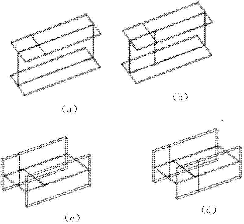
[0029] Embodiment 1. Cutting method 1 of Z-shaped incision of H-shaped steel. The cutting method is attached figure 2 (a)- figure 2 (d) shown.

[0030] Step 1, as attached figure 2 As shown in (a), for the H-shaped steel placed in the horizontal direction of the web, cut the web of the H-shaped steel according to the middle trimming edge of the Z-shaped incision (that is, the vertical in the Z stroke).

[0031] Specifically, the present invention should determine the specific position of the middle trimming edge of the Z-shaped slit according to the length of the actual required H-shaped steel, such as for a 12-meter-long H-shaped steel, it needs to be cut into 7 meters long according to actual construction requirements and two sections of 5-meter-long H-shaped steel with Z-shaped cuts, so that the intersection of 7 meters and 5 meters of the web of the 12-meter-long H-shaped steel is the specific position of the middle trimming.

[0032] The present invention can be cu...

Embodiment 2

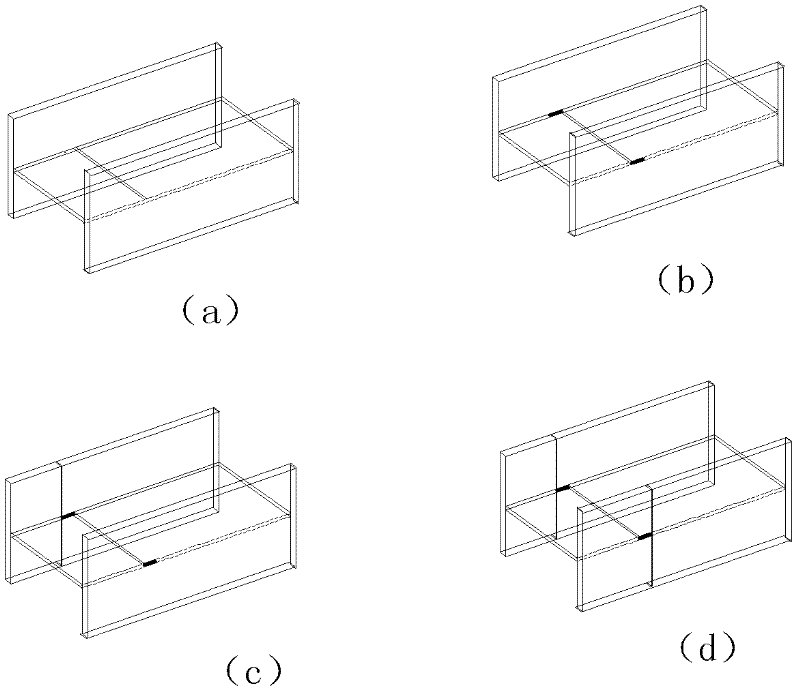
[0039] Embodiment 2, the cutting method 2 of the Z-shaped incision of the H-shaped steel.

[0040] This embodiment is basically the same as the first embodiment above, and the difference includes that the execution order of the steps in this embodiment is different from that in the first embodiment, that is, in this embodiment, the part of the connection between the web and the wing is peeled off first, Then cut through the web, and finally cut the flanges on both sides, specifically:

[0041] Step 1. For the H-shaped steel placed in the horizontal direction of the web, cut the joints between the web of the H-shaped steel and the flanges on both sides according to the two sides of the Z-shaped incision (that is, the two horizontal lines in the Z stroke) to peel off Partial connection of the web and side flanges.

[0042] Specifically, for one of the trimming edges on both sides, the joint between the web and the flange of the H-shaped steel is cut from the pre-cutting point o...


PUM


Abstract

The invention relates to a cutting method of a Z-shaped notch of H-shaped steel. The H-shaped steel is placed in the horizontal direction of a web plate. One cutting method comprises the following steps: firstly, cutting the web plate of the H-shaped steel according to the middle cutting edge of the Z-shaped notch; then cutting joints of the web plate of the H-shaped steel and wing plates at two sides respectively according to cutting edges at two sides of the Z-shaped notch so as to peel off partial connection between the web plate and the wing plates at two sides; and finally cutting the wing plates at two sides to form two sections of H-shaped steel with Z-shaped notches. The other cutting method is basically the same as the cutting method, and the only difference between the two cutting methods is that the execution sequence of the first cutting step and the second cutting step is changed. The technical scheme provided by the invention can be used for effectively avoiding adverse effects caused by internal stress in the cutting process and reducing the investment in lifting operation, thereby improving the cutting yield of the H-shaped steel, improving the working efficiency, and reducing the construction cost.

Description

technical field [0001] The invention relates to the cutting technology of H-shaped steel, in particular to a cutting method of Z-shaped incision of H-shaped steel. Background technique [0002] The H-shaped steel is composed of two side flanges and a middle web, and it is named because its section is the same as the English letter "H". Since all parts of the H-shaped steel are arranged at right angles, the bending resistance of the H-shaped steel is strong in all directions. In addition, H-shaped steel also has the advantages of simple construction, cost saving and light structure weight. At present, H-shaped steel has been widely used as an economical and efficient section with a more optimized cross-sectional area distribution and a more reasonable strength-to-weight ratio. [0003] Cutting is usually involved in the actual use of H-shaped steel. At present, the cutting method of Z-shaped incision of H-shaped steel, especially large-scale H-shaped steel with a web width ...

Claims


Application Information

Patent Timeline
IPC IPC(8): B23K7/00
Inventor 曹秀明
Owner 中色十二冶金建设有限公司
Why Eureka
Try Eureka