Yarn trapper for sewing machine

A thread tensioner and sewing machine technology, which is applied to sewing equipment, sewing machine components, sewing machine control devices, etc., can solve problems such as high heat generation, adjustment of clamping force, and impact on the service life of the thread tensioner, so as to prolong the service life, The effect of preventing overheating and accurate adjustment

Inactive Publication Date: 2012-08-15
NINGBO SUPREME ELECTRONIC MASCH INC
View PDF10 Cites 13 Cited by
  • Summary
  • Abstract
  • Description
  • Claims
  • Application Information

AI Technical Summary

Problems solved by technology

However, the existing tensioner cannot conveniently adjust the clamping force, and the coil of the electric touch iron will continue to conduct current for a long time during the working process, so the heat is large, which affects the service life of the tensioner

Method used


Image

  • Yarn trapper for sewing machine
  • Yarn trapper for sewing machine
  • Yarn trapper for sewing machine

Examples


Embodiment 1

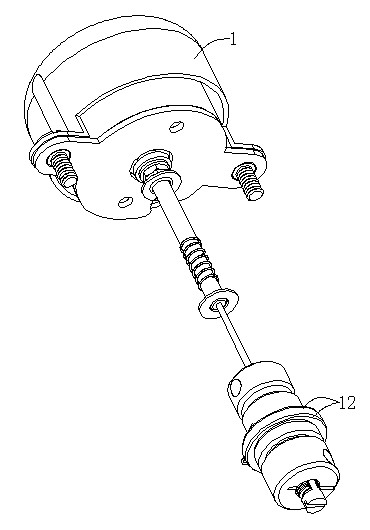
[0022] A thread gripper for a sewing machine usually includes two tension discs 12 for clamping sutures. The two tension discs 12 are arranged on the installation shaft in series, and the two tension discs 12 are driven to each other by the electromagnet 1. Clamping, the suture can maintain proper tension when the sewing machine is working.

[0023] The thread tensioner in this embodiment includes a thread tension disk 12 for thread tension, an electromagnet 1 for driving the thread tension disk 12 to clamp the thread, and a control circuit for driving the electromagnet 1 to act.

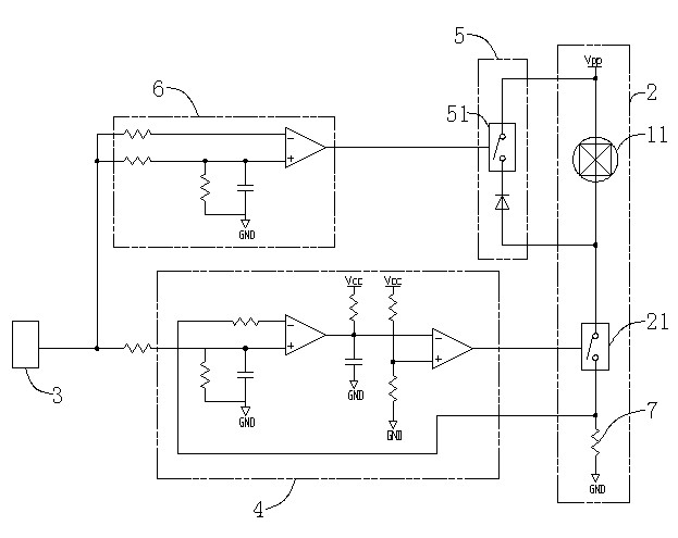
[0024] The control circuit is provided with a drive circuit 2 connected to the coil 11 of the electromagnet 1 . The drive circuit 2 can provide power to the coil 11 to make the electromagnet 1 work to drive the two clamping discs 12 to clamp each other.

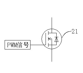
[0025] The driving circuit 2 is connected with a driving switch module 21 for controlling the current of the coil 11 to be turned on or off insta...

Embodiment 2

[0029] This embodiment is a further improvement on the basis of Embodiment 1. In this embodiment, the control circuit includes a driving circuit 2 and a driving switch module 21, and is provided with a signal generating circuit 3 for generating an analog signal and a PWM signal generating circuit 4 for generating an adjustable duty cycle.

[0030] When the wire clamping is required, the signal generating circuit 3 outputs an analog control signal.

[0031] The PWM signal generating circuit 4 receives the analog control signal, and outputs a PWM signal corresponding to the duty cycle according to the level value of the analog control signal.

[0032] The driving switch module 21 receives the PWM signal, and responds to instantaneously turn on the current or turn off the current according to the PWM signal.

[0033] The control circuit of this embodiment realizes controlling the ratio of the instantaneous on-current to the instantaneous off-current in the coil 11 through an ana...

Embodiment 3

[0036] This embodiment is a further improvement on the basis of Embodiment 2. In this embodiment, the control circuit is provided with a release circuit 5 connected to the coil 11 . When the drive circuit 2 cuts off the current of the coil 11, or the current in the coil 11 suddenly decreases, the release circuit 5 is turned on, so that the inductive energy storage of the coil 11 can be released as soon as possible to avoid electromagnetic interference to the circuit.

[0037] A release switch module 51 may also be provided in the release circuit 5 . When the thread tensioner is in normal working state, the release switch module 51 disconnects the release circuit 5 . When the drive circuit 2 cuts off the current of the coil 11 or the current in the coil 11 suddenly decreases, the release switch module 51 turns on the release circuit 5 to release the inductive energy storage of the coil 11 .


PUM


Abstract

The invention discloses a yarn trapper for a sewing machine. The yarn trapper comprises an electromagnet used for driving a yarn trapping disc to trap a yarn and a control circuit for driving the electromagnet to act; the control circuit is provided with a driving circuit connected with a coil in the electromagnet in design; the driving circuit is connected with a driving switch module for controlling the transient on or transient off of the current of the coil; and when the yarn trapping disc is used for trapping a yarn, the driving switch module controls the driving force of the electromagnet by controlling the ratio of the transient on current to the transient off current in the coil. When the ratio of the transient on current to the transient off current in the coil is high, the trapping force of the yarn trapping disc is large. When the ratio of the transient on current to the transient off current in the coil is small, the trapping force of the yarn trapping disc is small. In addition, the adjustment manner in such a way is convenient for effectively controlling the temperature of the coil when the electromagnet works and can be used for preventing the temperature of the coil from being overhigh, and prolonging the service life of the yarn trapper.

Description

technical field [0001] The invention relates to a thread clamp for a sewing machine, in particular to a thread clamp for clamping a sewing thread of a sewing machine so that the thread maintains a proper tension. Background technique [0002] A thread clamp is provided on the sewing machine, and the thread clamp needs to clamp the suture during sewing to give the suture an appropriate clamping force. If the clamping force is too large, when the needle guides the thread to sew, the tension on the thread will be too large, and the thread will easily break. If the clamping force is too small, the tension on the suture will be too small when the needle guides the suture to sew, which will affect the stitch quality. [0003] Existing thread tensioners generally include two tension discs and electromagnets for thread tension. Two clamp discs are movably arranged on the installation shaft. The electromagnet is connected with a driving rod, and the driving rod drives the two clam...

Claims


Application Information

Patent Timeline
Patent Type & Authority Applications(China)
IPC IPC(8): D05B47/04D05B69/00
Inventor 罗千
Owner NINGBO SUPREME ELECTRONIC MASCH INC
Why Eureka
Try Eureka