Method and system for oil life monitoring

A technology of engine oil and engine, which is applied in the directions of lubricating indicator devices and lubricating parts, and can solve problems such as jamming, engine component wear, loss of sufficient lubricating engine, etc.

Inactive Publication Date: 2012-08-15
GM GLOBAL TECH OPERATIONS LLC
View PDF6 Cites 16 Cited by
  • Summary
  • Abstract
  • Description
  • Claims
  • Application Information

AI Technical Summary

Problems solved by technology

At the end of its useful life, the oil can lose its ability to...

Method used


Image

  • Method and system for oil life monitoring
  • Method and system for oil life monitoring
  • Method and system for oil life monitoring

Examples


Embodiment Construction

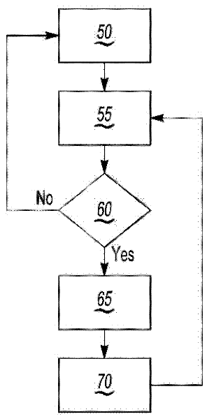
[0020] Referring to the drawings, wherein like reference numerals indicate like parts throughout the several views, Figure 1-3 The elements in are not necessarily to size or scale. Accordingly, the specific representations, dimensions and applications provided in the drawings presented herein should not be considered limiting.

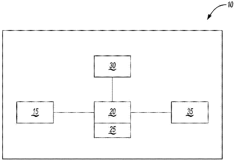
[0021] figure 1 is a schematic diagram of the system indicated generally at 10 . System 10 includes controller 20 and engine 15 . The controller 20 includes an algorithm 25 , wherein the algorithm 25 may be configured to generate an oil change index and a maximum oil change limit for the engine 15 . Controller 20 may be defined by one or more engine control modules (not shown) (also referred to as engine control units) and oil life monitor modules (not shown) (also referred to as oil life monitors or lubrication control modules) .

[0022] Controller 20 may further be configured to be in operative communication with, or defined by, one or more of...


PUM


Abstract

A method and system of determining a maximum oil change limit for an engine considering the engine operating environment and location is provided. An engine location indicator is generated in response to a trigger, using a locating device in communication with a controller. The locating device may include a global positioning system (GPS) receiver. The engine may be an internal combustion engine on a vehicle configured as one of a hybrid vehicle and an extended range electric vehicle. The trigger may be one of a calendar time, a key-on event, an oil change event, and a signal provided by the controller. The controller may generate the maximum oil change limit of the engine using one or more oil change indices, each defined by the engine location and/or time in location. The maximum oil change limit and/or an oil change limit alert may be provided as an output of the controller.

Description

technical field [0001] The present invention relates to a method and system for determining an oil change limit for an engine. Background technique [0002] The oil filter assembly and lubricating oil for the vehicle's internal combustion engine (ICE) are consumables that have a limited useful life and thus require periodic replacement during the life of the engine to avoid damage to the engine and / or associated engine components. damage. At the end of its useful life, the oil can lose its ability to adequately lubricate the engine, and engine components can wear or seize. An oil filter assembly, also commonly referred to as an oil filter, or filter, at the end of its useful life, may lose its ability to filter impurities from the oil, water degradation of the filter media may occur, the filter may become clogged, and Oil flow through the engine is reduced or stopped, or the filter may otherwise deteriorate so that oil is leaked from the engine through the canister, connec...

Claims


Application Information

Patent Timeline
IPC IPC(8): F01M11/10
CPCF01M11/10
Inventor R.L.贾奎斯M.J.斯奈德A.E.布克齐恩斯基
Owner GM GLOBAL TECH OPERATIONS LLC
Why Eureka
Try Eureka