Absolute time delay calibration system of inter-satellite link antennas of navigational satellites

A technology of inter-satellite links and antennas, which is applied in satellite radio beacon positioning systems, radio wave measurement systems, measurement devices, etc., can solve the problems of inability to correctly reflect the time delay of spread spectrum ranging signals, test connection cable waveguide length, It is difficult to obtain standard antennas and other issues, so as to eliminate the influence of delay calibration accuracy, avoid technical implementation difficulties, and achieve simple delay calibration

Active Publication Date: 2012-08-15
BEIJING INST OF SPACECRAFT SYST ENG
View PDF4 Cites 18 Cited by
  • Summary
  • Abstract
  • Description
  • Claims
  • Application Information

AI Technical Summary

Problems solved by technology

The delay calibration system uses a standard antenna as a test reference. For navigation satellite inter-satellite link ka-band antennas, it is difficult to obtain a standard antenna for testing delay. When testing a road analyzer, the test connecting cable or waveguide is long. In the case of Ka frequency band operation, it is very difficult to ensure the stability and high precision of the delay calibration of the long test cable or waveguide.
One of the most important is: the delay value tested by the vector network analyzer is the group delay of each test frequency point in a frequency band, which cannot correctly reflect the spread spectrum ranging signal of a specific signal system transmitted by the inter-satellite link. Latency

Method used


Image

  • Absolute time delay calibration system of inter-satellite link antennas of navigational satellites
  • Absolute time delay calibration system of inter-satellite link antennas of navigational satellites
  • Absolute time delay calibration system of inter-satellite link antennas of navigational satellites

Examples


Embodiment Construction

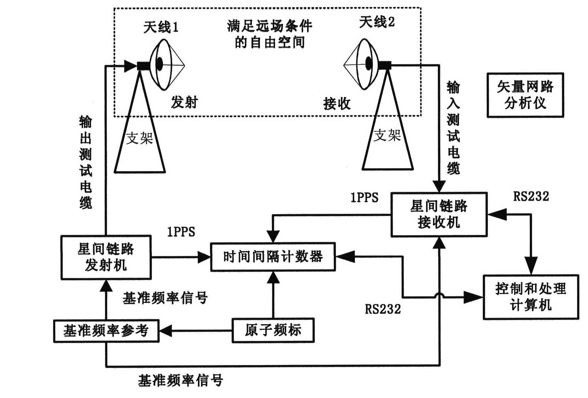
[0027] like figure 1 As shown, it is a structural diagram of the calibration system of the present invention, which consists of a reference frequency source, an inter-satellite link transmitter, an inter-satellite link receiver, a time interval counter, a control and processing computer, an attenuator, an output test cable, and an input test Cables, antenna mounting brackets, vector network analyzers and at least three inter-satellite link antennas to be calibrated. The functions of each component are as follows:

[0028] Reference frequency source: Generate the same reference frequency signal as the satellite clock frequency of the navigation satellite, and provide frequency reference for the inter-satellite link transmitter and inter-satellite link receiver.

[0029] Inter-satellite link transmitter: Generate the ranging signal transmitted by the inter-satellite link, and provide a second pulse signal as an input of the time interval counter.

[0030] Inter-satellite link ...


PUM


Abstract

The invention provides an absolute time delay calibration system of inter-satellite link antennas of navigational satellites. The calibration system comprises a reference frequency source, an inter-satellite link transmitter, an inter-satellite link receiver, a time interval counter, a controlling and processing computer, an attenuator, a vector network analyzer and at least three inter-satellitelink antennas to be calibrated. The inter-satellite link antennas to be calibrated are subjected to pair-wise coupling mutually and are formed as a transceiving link together with the inter-satellitelink transmitter, the inter-satellite link receiver, the attenuator and the cables therebetween. The time interval counter measures the time difference between second signals generated by the inter-satellite link transmitter and the inter-satellite link receiver respectively. The controlling and processing computer reads measurement valves of the inter-satellite link receiver and the time interval counter so as to obtain the absolute time delay of each inter-satellite link antenna to be calibrated after data processing. The calibration system provided by the invention adopts test signals which accord with an inter-satellite link transmission signal system; a practical inter-satellite signal transmission time delay can be reflected in the test result, so that the calibration system is higher in measurement precision.

Description

technical field [0001] The invention relates to a system for calibrating the absolute time delay of an antenna of an inter-satellite link of a navigation satellite, which can be used for calibrating the absolute time delay of an antenna of an inter-satellite link of a navigation satellite system. Background technique [0002] In the global satellite navigation system, maintaining high satellite orbit determination accuracy and clock error determination accuracy is the key to ensure that the navigation receiving terminal obtains the positioning or timing accuracy required by the large system. Obtaining precise orbit and clock error parameters usually requires the deployment of a large number of ground stations around the world for continuous observation. At present, my country does not have such global strategic geographic resources. Therefore, the global satellite navigation system under research in my country will use inter-satellite link technology, among which An important...

Claims


Application Information

Patent Timeline
Patent Type & Authority Applications(China)
IPC IPC(8): G01S19/20
Inventor 崔小准刘家兴董海青武向军钟兆丰
Owner BEIJING INST OF SPACECRAFT SYST ENG
Why Eureka
Try Eureka