Cooling system and fuel cell stack

A fuel cell stack and cooling system technology, which is applied to fuel cells, fuel cell grouping, fuel cell additives, etc., and can solve problems such as uneven temperature distribution

Inactive Publication Date: 2012-08-15
中国东方电气集团有限公司
View PDF8 Cites 9 Cited by
  • Summary
  • Abstract
  • Description
  • Claims
  • Application Information

AI Technical Summary

Problems solved by technology

[0005] The purpose of the present invention is to provide a cooling system and a fuel cell stack to solve the problem of uneven temperature

Method used


Image

  • Cooling system and fuel cell stack
  • Cooling system and fuel cell stack
  • Cooling system and fuel cell stack

Examples


Example Embodiment

[0030] It should be noted that the embodiments in this application and the features in the embodiments can be combined with each other if there is no conflict. Hereinafter, the present invention will be described in detail with reference to the drawings and in conjunction with the embodiments.

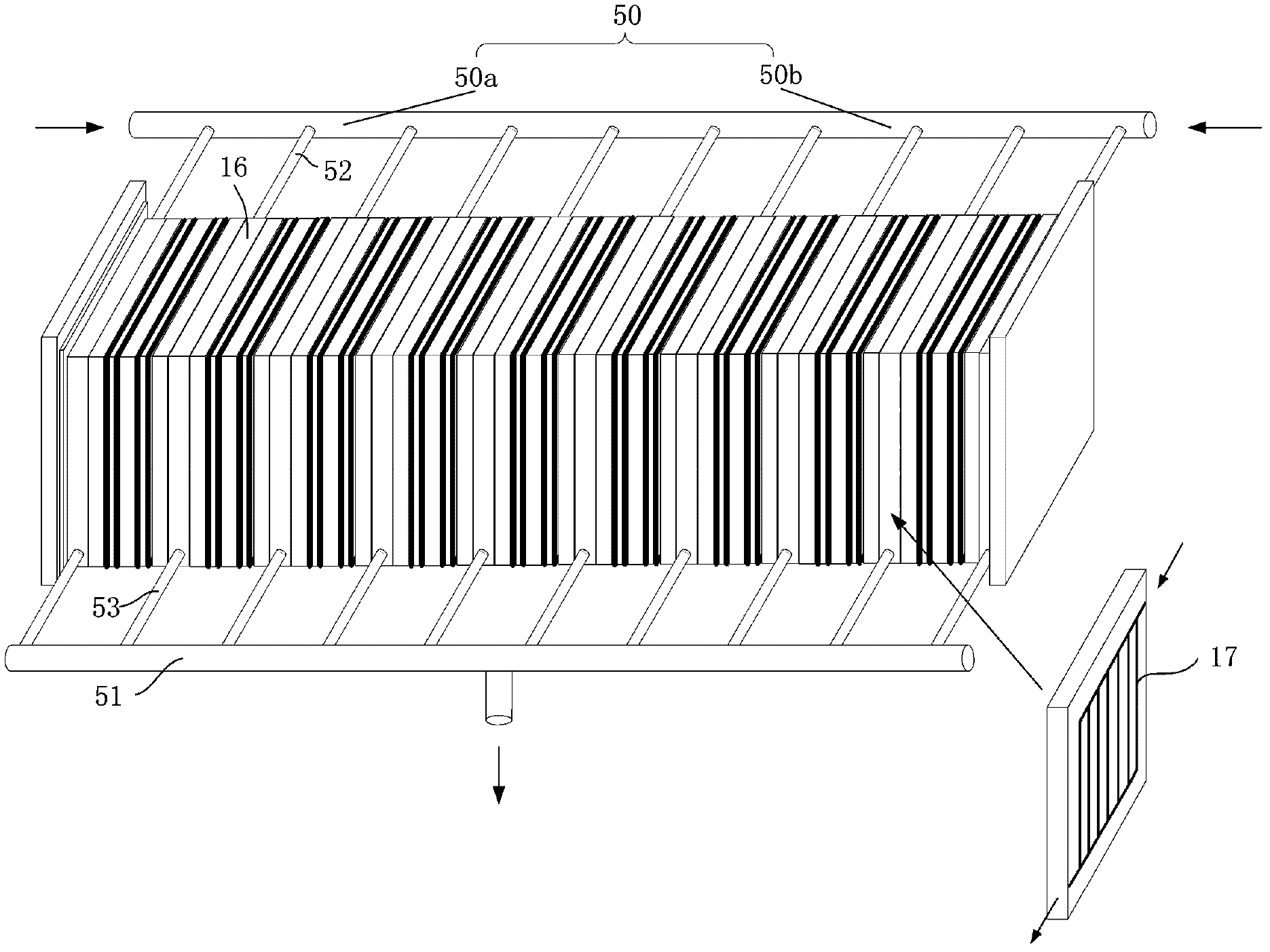
[0031] Such as figure 1 As shown, the cooling system of the first embodiment includes: a liquid inlet pipe and a liquid outlet pipe, and the liquid outlet is connected with the liquid inlet through a circulation loop to form a cooling circulation loop of the fuel cell. The liquid inlet pipe includes: a liquid inlet main pipe 50 and a liquid inlet branch pipe 52. The liquid inlet main pipe 50 has two liquid inlets located at the upstream end, and the liquid inlets are located at both ends of the liquid inlet main pipe 50; a plurality of liquid inlet branch pipes 52 are connected Between the inlet main pipe 50 and the fuel cell stack body 1; the outlet pipe includes: an outlet main pipe 51 ...


PUM


Abstract

The invention provides a cooling system and a fuel cell stack. The cooling system comprises a liquid inlet pipe, multiple liquid inlet branch pipes, a liquid outlet pipe and multiple liquid outlet branch pipes, wherein the liquid inlet pipe comprises a liquid inlet main pipe which is provided with liquid inlets at an upstream end, the liquid inlets are arranged at two ends of the liquid inlet main pipe, the multiple liquid inlet branch pipes are connected between the liquid inlet main pipe and a fuel cell stack body; the liquid outlet pipe is provided with a liquid outlet at a downstream end, the liquid outlet is arranged at the middle part of the liquid outlet pipe; and multiple liquid outlet branch pipes are connected between the liquid outlet main pipe and the fuel cell stack body, wherein the liquid outlet is connected with the liquid inlets through a circulation loop so as to form a cooling circulation loop of the fuel cell. The cooling system and the fuel cell stack provided by the invention can effectively solve the problem of uneven temperature distribution between a single battery of a fuel stack end plate and a single battery of a middle position in the prior art.

Description

technical field [0001] The invention relates to the technical field of fuel cell cooling, in particular to a cooling system and a fuel cell stack. Background technique [0002] A fuel cell is an electrochemical reaction device that can directly and efficiently convert the chemical energy of reactants into electrical energy. Fuel cells have the advantages of high energy conversion efficiency, no pollution, continuous power supply, and high reliability, and are widely used in aerospace, military, electric vehicles, uninterruptible power supplies and other fields. [0003] In the fuel cell of the prior art, the fuel is continuously input into the anode (negative electrode), and at the same time, the oxidant is continuously input into the cathode (positive electrode), and an electrochemical reaction occurs on the two electrodes to generate electric current. The basic physical structure of a fuel cell consists of an electrolyte layer flanked by electrode layers. Among them, the...

Claims


Application Information

Patent Timeline
IPC IPC(8): H01M8/04H01M8/24H01M8/04029H01M8/249
CPCY02E60/50
Inventor 王晶王荣贵曹立勇李婷殷聪谢光有
Owner 中国东方电气集团有限公司
Why Eureka
Try Eureka