Device and method for converting circular motion

A kind of arc motion and motion conversion technology, applied in transmission, medical science, brushes, etc., can solve the problems of difficult application, low efficiency, etc., and achieve the effect of stabilizing the driving relationship and solving the load and fault.

Inactive Publication Date: 2012-08-15
MAXROTEC
View PDF8 Cites 0 Cited by
  • Summary
  • Abstract
  • Description
  • Claims
  • Application Information

AI Technical Summary

Problems solved by technology

[0005] As mentioned above, the conventional technology generally uses the movement direction of the eccentric rotary motion of the eccentric cam to be converted once. However, although this technology can be easily applied to structures that require relatively small forces, it is relatively difficult to use. High power and rotational force, in mechanical devices with high resistance to final drive, many problems arise due to a lot of direct load on the eccentric cam, and there is a problem of inefficiency
[0006] In addition, in order to increase the movement range of the final moving parts, the radius of rotation of the eccentric cam needs to be increased, but the larger the radius of rotation, the greater the telecentric force will be generated on the eccentric cam, so it is actually difficult to apply to applications requiring high RPM used in devices or devices with a large range of movement of the final moving parts

Method used


Image

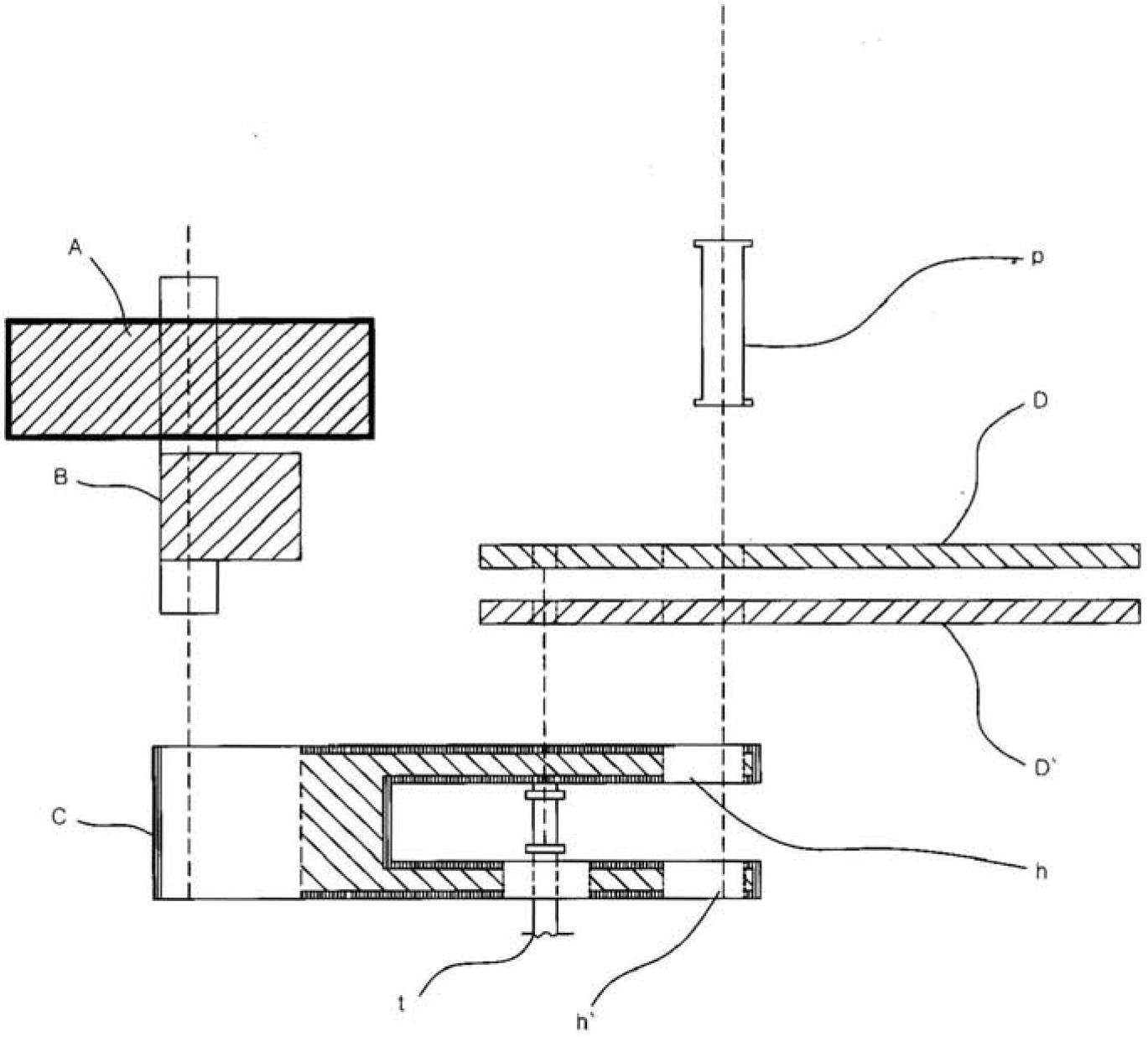
  • Device and method for converting circular motion
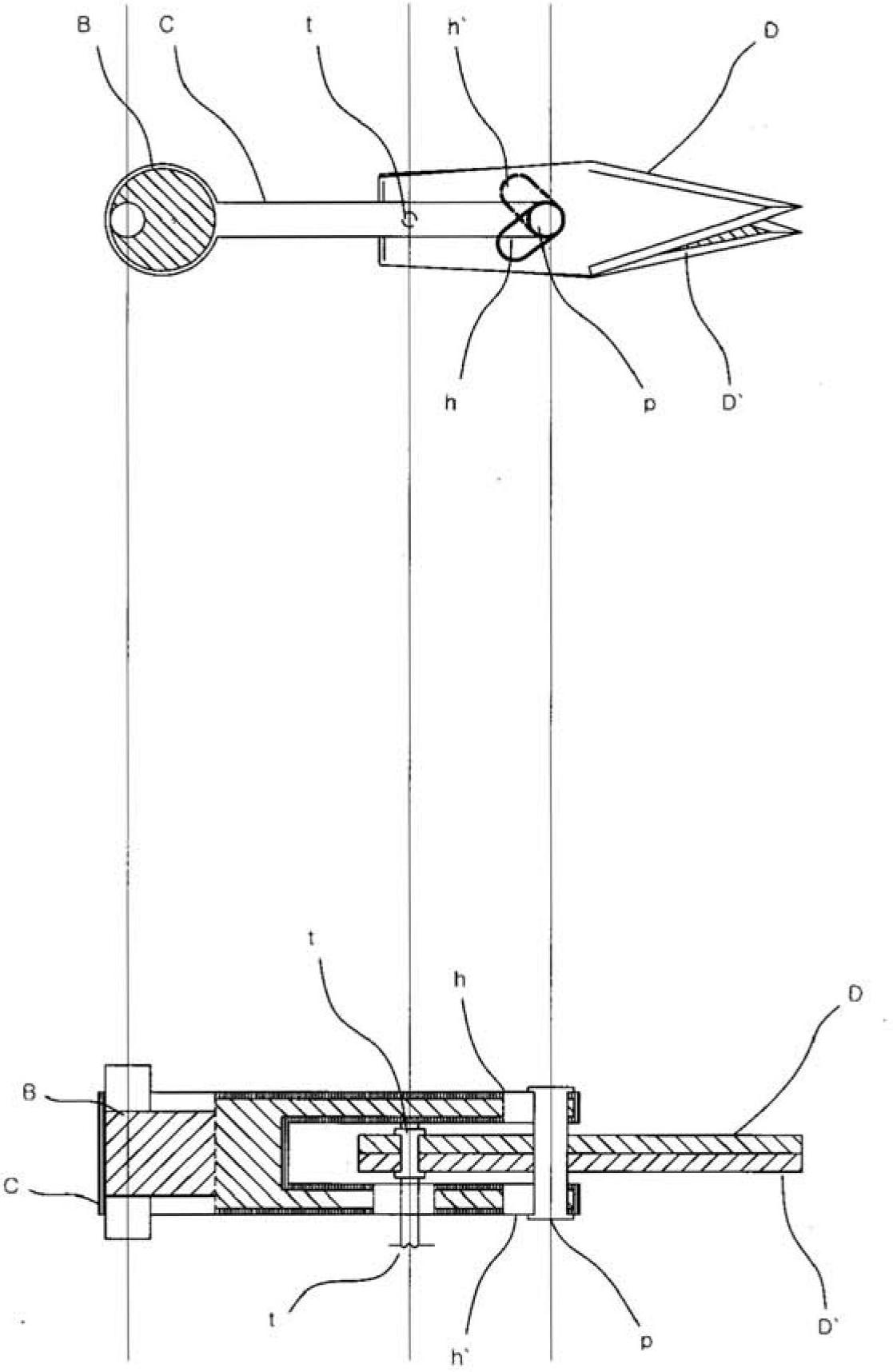
  • Device and method for converting circular motion
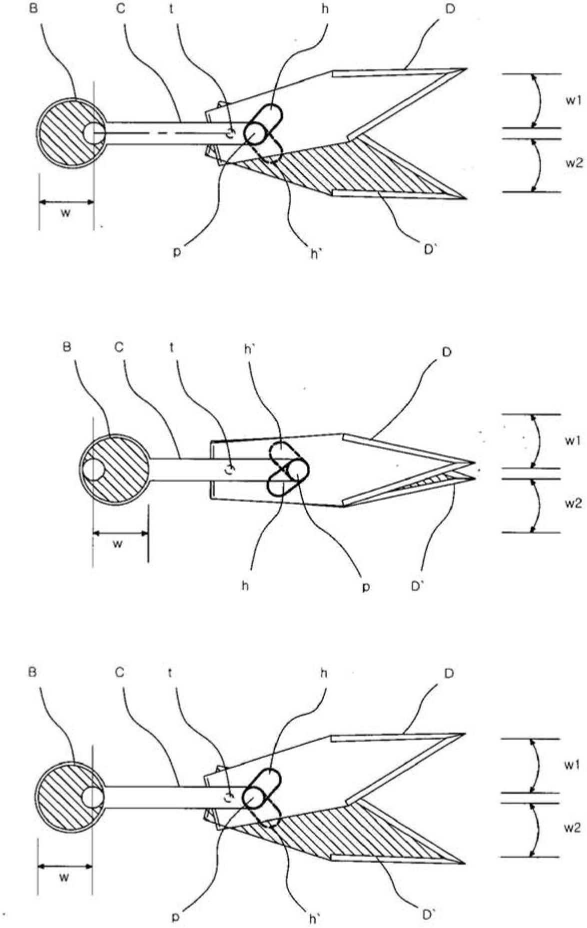
  • Device and method for converting circular motion

Examples


Embodiment Construction

[0025] When the rotary power is generated by an internal combustion engine, a motor, etc. as a general rotary power generating device, the power is transmitted through various gears, cams, shafts, etc. In the mechanical device used to convert the direction of this rotary motion, the eccentric cam is often used to convert the direction of motion.

[0026] As briefly explained in the previous prior art, the above-mentioned method is applied to the motion conversion of various mechanical devices, so in devices that use eccentric cams to convert rotational motion into other motion directions, it is a fact that generally It is used for one conversion, that is, converting eccentric rotation motion into motion in various directions.

[0027] In the present invention, such motion can be applied to various mechanical devices in order to improve efficiency and stability in use in the device and method for converting eccentric rotary motion into arc motion. Use, in the power unit that p...


PUM


Abstract

The present invention relates to a device and a method for converting the direction of rotary motion generated at a torque generation means such as a motor and the like into linear motion and re-converting the same into circular motion. The present invention relates to a device and a method for converting circular motion, wherein an eccentric cam (B) is interlocked with one side by a drive unit (A) or the like comprising a power transmission means such as a rotating shaft, a gear, and the like rotated by a torque generation means to transmit torque, and is rotated (first eccentric rotary motion). Three-dimensional circular motion is carried out by a connection rod (C) connected to one side of the eccentric cam (B) to do second straight reciprocating motion, drive grooves (h, h') connected with the connection rod (C) by a binding means such as a pin (p) and the like, and an up-and-down motion converting member (D) of which one side is fixed to a hinge axis (t), wherein circular motion is carried out by amplifying the rotary motion of the eccentric cam, and as a result eccentric rotary motion is finally converted into rectilinear motion and the same is re-converted into the amplified circular motion.

Description

technical field [0001] The present invention relates to a device and method for converting the motion direction to arc motion after converting eccentric rotary motion into linear motion, and maximizing the use of the radius of rotation of the eccentric cam to finally utilize the amplified arc motion. The device and method as follows: After converting the eccentric rotary motion into linear motion, when it is converted into arc motion again, the radius of rotation of the eccentric cam is utilized to the greatest extent and efficiently to amplify the amount of circular motion of the final moving part , so that the mechanical device and method utilizing these can be applied. Background technique [0002] In general, various machines have been developed that use an eccentric cam that rotates in conjunction with rotational power supplied by an internal combustion engine or electricity to switch the direction of motion. That is, a device that generally uses a method based on one-...

Claims


Application Information

Patent Timeline
Patent Type & Authority Applications(China)
IPC IPC(8): A46B13/02A61C17/16
CPCA61C17/16F16H25/18F16H37/12Y10T74/1828A46B13/02
Inventor 金元泰
Owner MAXROTEC
Why Eureka
Try Eureka