Foam elimination device for vacuum oil purification

A foam and vacuum technology, applied in the direction of foam dispersion/prevention, can solve problems such as safety accidents, threats to staff safety, fire threats to equipment personal safety, etc., to achieve the effect of eliminating foam and advanced and reasonable structure

Active Publication Date: 2012-08-22
高存兴
View PDF5 Cites 4 Cited by
  • Summary
  • Abstract
  • Description
  • Claims
  • Application Information

AI Technical Summary

Problems solved by technology

[0002] At present, in the process of vacuum oil purification, when the processed oil enters the vacuum tank under negative pressure from the normal pressure state, due to the change of pressure and the influence of impurities in the oil (gas, liquid and solid impurities) Affected by various factors such as temperature and temperature, a large number of bubbles will be generated after the treated oil enters the vacuum tank. Because it cannot be eliminated, the foam will grow rapidly within the height of the vacuum tank. When the height of the foam reaches the vacuum pump When the air suction port of the air pipeline is used, the foam will be drawn out from the air suction line by the vacuum pump and discharged from its exhaust port by the vacuum pump. After the foam is discharged by the vacuum pump, it will return to the state of oil under normal pressure, and the oil will be discharged. Afterwards, it will cause environmental pollution; threaten the safety of staff; increase processing costs and production costs; serious will cause fire threats to equipment and personal safety or even greater safety accidents
At present, there is no good solution in the process of vacuum oil purification at home and abroad, and only negative control methods can be used to work, so that there are great hidden dangers in the vacuum oil purification work.

Method used


Image

  • Foam elimination device for vacuum oil purification
  • Foam elimination device for vacuum oil purification
  • Foam elimination device for vacuum oil purification

Examples


Embodiment Construction

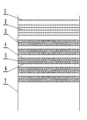
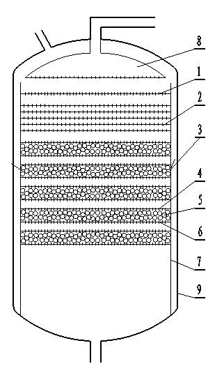
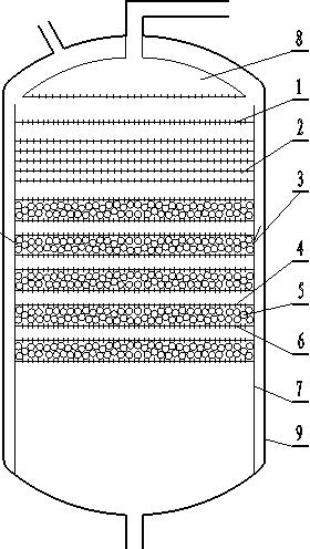
[0013] see figure 1 , figure 2 , Vacuum clean oil foam elimination device. It is composed of a deflector, a stainless steel screen, a chromatography device, and a bracket 7, and the bracket 7 is connected with a deflector 1, five layers of stainless steel screens 2, and five sets of chromatography devices 3 sequentially from top to bottom. The deflector 2 is made of a stainless steel plate with a thickness of 1.5mm, and a plurality of holes with a diameter of 3mm are processed on the plate. The diameter of the hole on the stainless steel screen 3 is 1 mm, and the distance between the five layers of stainless steel screen 3 is 10 mm. The chromatography device 3 is composed of an upper deflector 4, a high-elastic fiber ball 5, and a lower deflector 6 connected in sequence, and the distance between the upper deflector 4 and the lower deflector 6 is 30mm, and the middle is placed There are high-elastic fiber balls 5 with a diameter of 10 mm, and the distance between five sets ...


PUM

PropertyMeasurementUnit
thicknessaaaaaaaaaa
diameteraaaaaaaaaa
diameteraaaaaaaaaa

Abstract

The invention discloses a foam elimination device for vacuum oil purification, which comprises guide plates, stainless steel meshes, chromatography devices and a bracket, wherein the bracket is successively connected with the guide plates, five layers of stainless steel meshes and five sets of chromatography devices from top to bottom; the guide plate is made of a stainless steel plate of which the thickness is 1.5mm; a plurality of holes of which the diameter is 3mm are processed in the plate; the diameter of holes in the stainless steel meshes is 1mm; space between every two layers of stainless steel meshes is 10mm; each chromatography device is formed by successively connecting an upper guide plate, a high-elastic fiber ball and a lower guide plate; the space between the upper guide plate and the lower guide plate is 30mm; the middle is provided with a high-elastic fiber ball of which the diameter is 10mm; and the space between every two layers of chromatography devices is 20mm. The foam elimination device for vacuum oil purification has the advantages of reasonable and advanced structure, foam generated in a vacuum tank in the vacuum oil purification processing process can be effectively eliminated, and the safety and the environment protection in the vacuum oil purification processing process are greatly improved.

Description

technical field [0001] The invention relates to a foam elimination device for vacuum oil purification, which belongs to the technical field of oil purification. Background technique [0002] At present, in the process of vacuum oil purification, when the processed oil enters the vacuum tank under negative pressure from the normal pressure state, due to the change of pressure and the influence of impurities in the oil (gas, liquid and solid impurities) Affected by various factors such as temperature and temperature, a large number of bubbles will be generated after the treated oil enters the vacuum tank. Because it cannot be eliminated, the foam will grow rapidly within the height of the vacuum tank. When the height of the foam reaches the vacuum pump When the air suction port of the air pipeline is used, the foam will be drawn out from the air suction line by the vacuum pump and discharged from its exhaust port by the vacuum pump. After the foam is discharged by the vacuum p...

Claims


Application Information

Patent Timeline
Patent Type & Authority Applications(China)
IPC IPC(8): B01D19/02
Inventor 王福义葛国庆
Owner 高存兴
Why Eureka
Try Eureka