Rapid clamping drive plate

A chuck and fast technology, applied in the direction of clamping, supporting, positioning devices, etc., can solve the problems of many hours of work and high labor intensity, and achieve the effect of low labor intensity, reasonable structure and reliable clamping

Inactive Publication Date: 2012-08-22
TIANRUN IND TECH CO LTD
View PDF6 Cites 6 Cited by
  • Summary
  • Abstract
  • Description
  • Claims
  • Application Information

AI Technical Summary

Problems solved by technology

[0002] We know that when machining shaft workpieces on lathes, the center holes at both ends of the workpiece are mostly used to tighten the top axially. , because this kind of chicken heart clip ...

Method used


Image

  • Rapid clamping drive plate
  • Rapid clamping drive plate
  • Rapid clamping drive plate

Examples


Embodiment Construction

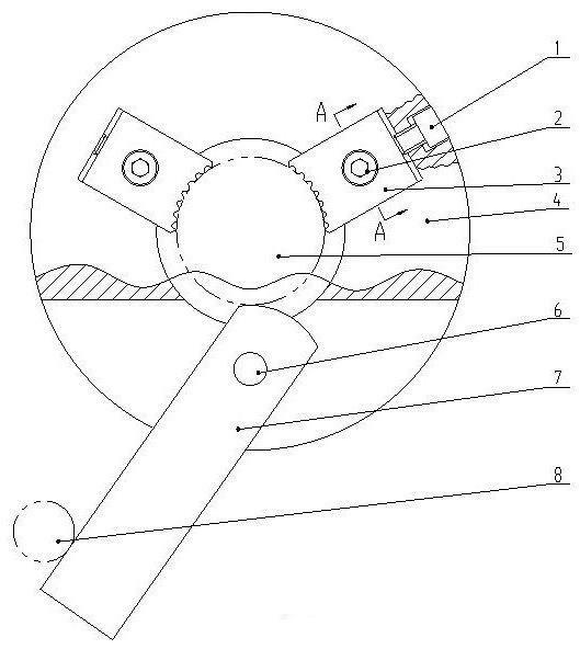
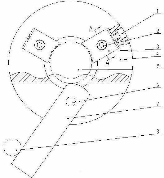
[0013] from figure 1 with figure 2 It can be seen that a quick clamping dial is provided with a chuck body 4, two claws 3, and an eccentric pressure rod 7. The chuck body 4 is axially provided with a round hole for fitting a workpiece 5. When in use, First, the chuck body 4 is inserted into the outer circle of the workpiece 5 .

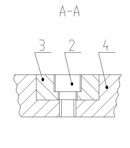
[0014] Two rectangular grooves are symmetrically arranged on the end surface of the chuck body 4 of the present invention, and the middle part corresponding to the rectangular grooves on the chuck body 4 is provided with a screw hole, and the middle part of the claw 3 is provided with a counterbore. Cooperating with the screw hole provided in the middle of the chuck body 4, the two claws 3 are respectively installed in the rectangular grooves of the chuck body 4, and the compression screw 2 is compressed and fixed. Such as figure 2 shown. The front end surface of the claw 3 protrudes radially from the circumferential surface of the circular hole...


PUM


Abstract

The invention relates to a rapid clamping drive plate. The rapid clamping drive plate comprises a clamping drive plate body, clamping jaws and an eccentric compression bar, wherein a circular hole for arranging a workpiece is axially arranged on the clamping drive plate body, two rectangular grooves are symmetrically installed on the end surface of the clamping drive plate body, the clamping jaws are installed in the rectangular grooves of the clamping drive plate body respectively through forcing screws, a semicircular groove is arranged on the lower portion of the clamping drive plate body, the eccentric compression bar is arranged in the semicircular groove of the clamping drive plate body through a hinge pin, the front end surfaces of the clamping jaws and the front end surface of the eccentric compression bar form three-point support in the circular hole circumference of the clamping drive plate body, the eccentric compression bar is rotated to press the workpiece tightly, and the workpiece arranged in the circular hole is clamped. During usage, when a spindle of the machine tool rotates, one side surface of the eccentric compression bar contacts a drive rod arranged on the machine tool, and the drive rod presses the eccentric compression bar to enable the workpiece to be clamped more tightly, therefore rotation is achieved. The rapid clamping drive plate has the advantages of being reasonable in structure, simple to manufacture, convenient to operate, low in labor intensity, reliable in clamping, and suitable for clamping of shaft diameters in different sizes.

Description

technical field [0001] The invention relates to a clamping device for shaft parts, in particular to a quick clamping dial. Background technique [0002] We know that when machining shaft workpieces on lathes, the center holes at both ends of the workpiece are mostly used to tighten the top axially. , because this kind of chicken heart folder adopts the screw thread compression structure, for mass production, the labor intensity is high, the consumption of man-hours is many, and it is not suitable for the processing of workpieces with different shaft diameters. Contents of the invention [0003] The technical problem to be solved by the present invention is to overcome the deficiencies of the above-mentioned prior art, and provide a quick clamping dial with reasonable structure, simple manufacture, convenient operation, low labor intensity, reliable clamping, and suitable for clamping with different shaft diameters. plate. [0004] The technical scheme adopted by the pres...

Claims


Application Information

Patent Timeline
IPC IPC(8): B23Q3/00
Inventor 丛建臣宋文友王丰奎武刚刘劲松
Owner TIANRUN IND TECH CO LTD
Why Eureka
Try Eureka