Al technical title is built by PatSnap Al team. It summarizes the technical point description of the patent document.
A spherical robot, fluid-driven technology, applied in the electromechanical field, can solve the problems of difficult engineering implementation, low practicability, complex structure, etc., and achieve the effect of no transmission loss, compact structure, and simplified driving device
Active Publication Date: 2016-08-24
TAISHAN UNIV
View PDF4 Cites 2 Cited by
Summary
Abstract
Description
Claims
Application Information
AI Technical Summary
This helps you quickly interpret patents by identifying the three key elements:
Problems solved by technology
Method used
Benefits of technology
Problems solved by technology
[0005] Although there have been many successful designs of spherical robots at home and abroad, and their driving mechanisms are various, most of them have the disadvantages of complex structure, difficult engineering realization and low practicability.
So far, no driving method has been publicly recommended by everyone, and there is no mature theoretical system for the research on the structure and driving method of spherical robots.
Method used
Image
Click on the blue label to locate the original text in one second.
Reading with bidirectional positioning of images and text.
Examples
Embodiment Construction
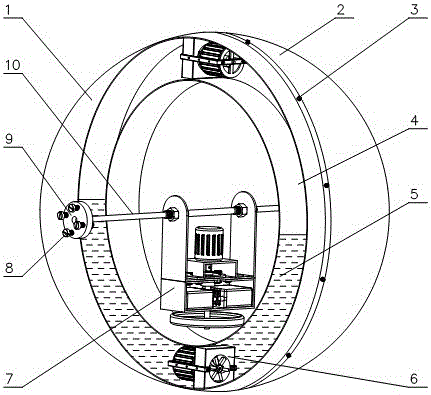
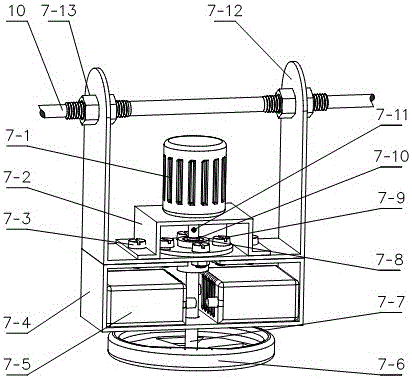
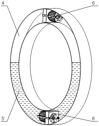
[0026] Such as figure 1 , 2 As shown, an embodiment of the present invention is: a fluid-driven omnidirectional motion spherical robot device, which mainly includes a left hemispherical shell 1, a right hemispherical shell 2, a square annular sealed container 4, an axial flow device 6, an internal drive rotation mechanism 7, The main shaft 10; the left and right hemispherical shells are fastened by screws 3, the square ring-shaped sealed container 4 is located inside the spherical shell, the outer ring surface of the container is concentric with the spherical surface of the spherical shell, and the fluid (usually liquid) is contained inside the container, and the volume of the fluid is equal to the volume of the container 1 / 2, two axial flow devices 6 are symmetrically installed inside the square annular sealed container, and the axial flow device drives the liquid 5 to flow in the square annular sealed container 4, thereby changing the center of mass of the spherical robot, t...
PUM
Abstract
The invention belongs to the field of electromechanical technology, and relates to a spherical mobile robot, in particular, to a fluid-driven spherical robot, which includes a spherical shell, an annular sealed container, an axial flow device, an internal drive rotation mechanism, and a main shaft; it is characterized in that: the spherical shell is composed of The left and right hemispherical shells are composed of two hemispherical shells; the annular sealed container is located inside the spherical shell, the outer ring surface of the container is concentric with the spherical surface of the spherical shell, and the fluid is contained inside the container, and the volume of the fluid is 1 / 2 of the volume of the container. The axial flow device drives the liquid to flow in the annular sealed container, thereby changing the center of mass of the spherical robot, thereby realizing the forward and backward of the spherical robot; the internal drive rotation mechanism located inside the spherical shell mainly includes: internal drive bracket, motor, Motor bracket, flywheel shaft, flywheel, power supply and controller, etc.; the main shaft is connected to the spherical shell through bearings, other parts of the internal drive rotation mechanism are suspended on the main shaft through the internal drive bracket, and the motor is fixed to the internal drive bracket through the motor bracket Connection, the flywheel is installed on the internal drive bracket through the bearing, the motor shaft and the flywheel are connected through the coupling, the motor drives the flywheel shaft and the flywheel whose lower part is perpendicular to the main shaft to rotate together, and realizes the steering of the fluid-driven spherical robot by using the principle of conservation of angular momentum .
Description
technical field [0001] The invention belongs to the field of electromechanical technology, and relates to a spherical robot with omnidirectional motion, which can be applied to the fields of detection, search and rescue, military affairs, transportation, entertainment and the like. Background technique [0002] A spherical robot is a robot with a spherical shell that walks in a rolling manner. Compared with wheeled robots, there is no problem of "overturning"; compared with walking or crawling robots, it has the characteristics of fast movement speed and strong carrying capacity . In addition, the spherical robot is flexible and has a small turning radius; the spherical robot has a novel and unique shape, flexible movement, and a small turning radius; the spherical structure has a strong self-recovery ability, and the spherical shell also enables the robot to easily roll over rough terrain. At the same time, since the resistance of ball rolling point contact is much smaller...
Claims
Application Information
Patent Timeline
Application Date:The date an application was filed.
Publication Date:The date a patent or application was officially published.
First Publication Date:The earliest publication date of a patent with the same application number.
Issue Date:Publication date of the patent grant document.
PCT Entry Date:The Entry date of PCT National Phase.
Estimated Expiry Date:The statutory expiry date of a patent right according to the Patent Law, and it is the longest term of protection that the patent right can achieve without the termination of the patent right due to other reasons(Term extension factor has been taken into account ).
Invalid Date:Actual expiry date is based on effective date or publication date of legal transaction data of invalid patent.