Mounting technology of large-module wall
An installation process and large module technology, which is applied in the processing of building materials, construction, building construction, etc., can solve the problems of long construction period and high cost of the installation process, so as to save formwork materials, reduce overall cost, and improve construction progress effect
- Summary
- Abstract
- Description
- Claims
- Application Information
AI Technical Summary
Problems solved by technology
Method used
Image

Examples
specific Embodiment approach 1
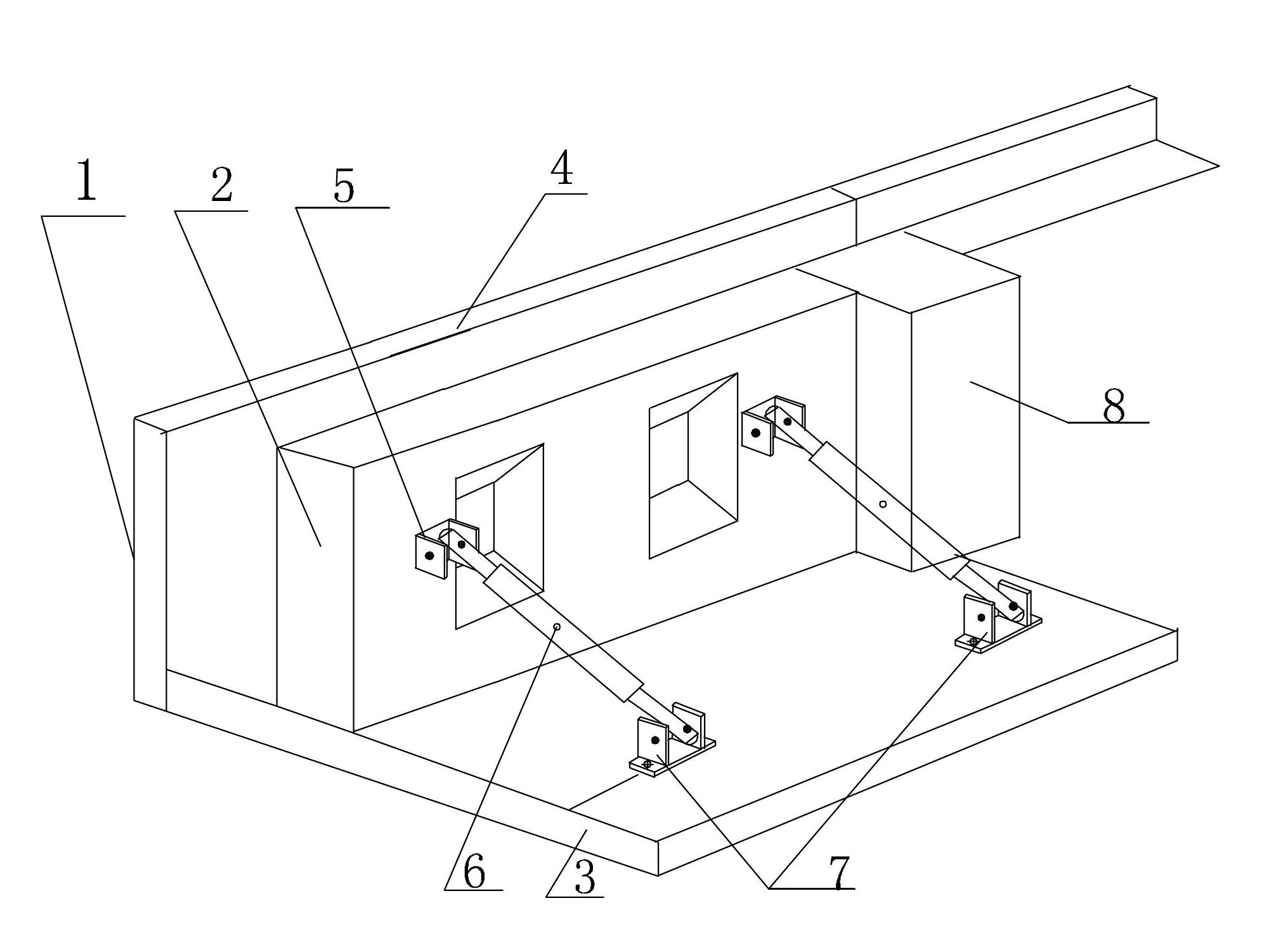
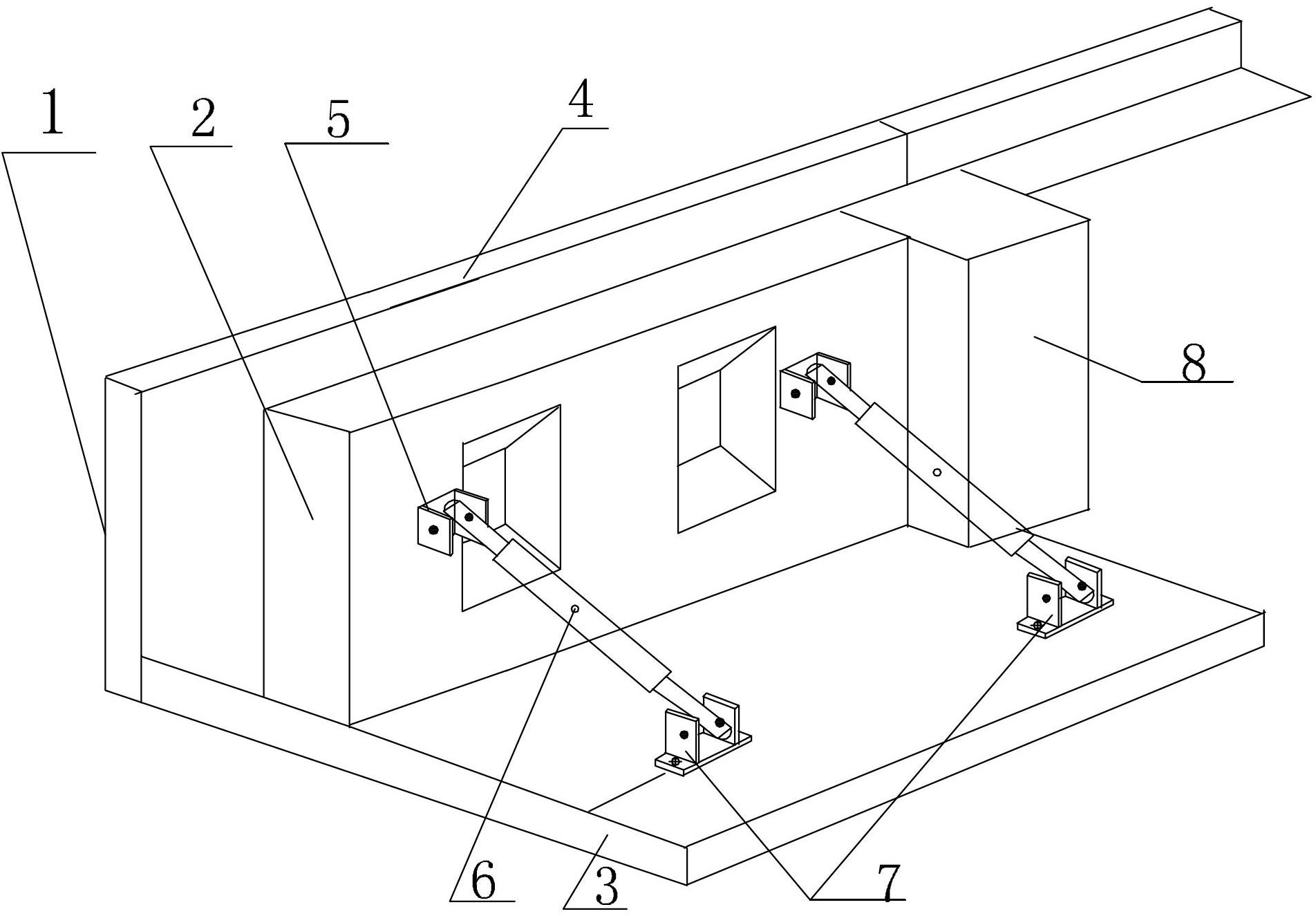
[0015] Embodiment 1: Combining figure 1 Describing this embodiment, the installation process of this embodiment is completed based on the following large modular wall 4, the large modular wall 4 includes an outer wall 1 and an inner wall 2, and the outer wall 1 and the inner wall 2 The vertical center lines overlap and the two are connected, the height and width of the inner wall 2 are smaller than the height and width of the outer wall 1, and the distance between the upper end face of the inner wall 2 and the upper end face of the outer wall 1 is 200mm -1000mm, the distance between the end faces on both sides of the inner wall 2 and the corresponding side end faces of the outer wall 1 is 20m-80mm; it is characterized in that the installation process includes the following steps:
[0016] Step 1. In the upper plane reference elastic line of the ring beam 3 to be installed on the wall, wet the entire upper plane of the ring beam 3 with clean water, and then evenly lay the cushi...
specific Embodiment approach 2
[0030] Specific embodiment 2: This embodiment also includes step 3' between steps 3 and 4: check the flatness of the large module wall 4 with a ruler rod and a plumb weight, the allowable error is ≤ 3mm, and the allowable error of verticality is ≤ 3mm, the bottom plane of the large module wall 4 is adjusted with a wedge-shaped wooden block to adjust the verticality of the wall, the expansion gap between the bottom plane of the large module wall 4 and the upper plane of the ring beam is adjusted to 20mm, and the adjustment screw 6 is used to adjust the large module wall. 4 flatness, after the verification is qualified, insert the wedge-shaped duckbill adjustment horn or the corresponding steel plate into the wall embedded parts and the ring beam embedded parts for firm welding. This step can effectively adjust the verticality of the wall. , Fill the horizontal gap with thermal insulation material or polyurethane foam, use low-temperature-resistant and elastic weather-resistant s...
specific Embodiment approach 3
[0031] Embodiment 3: In step 5 of this embodiment, a paper conical exhaust pipe is added every 500mm at the gap between two adjacent outer walls 1, and the large diameter end of the conical exhaust pipe is Set on the outside of the outer wall, this step can discharge the gas generated when the concrete is poured and avoid the generation of air bubbles. Other embodiments are the same as the first embodiment.
PUM
| Property | Measurement | Unit |
|---|---|---|
| Thickness | aaaaa | aaaaa |
Abstract
Description
Claims
Application Information
 - R&D
- Intellectual Property
- Life Sciences
- Materials
- Tech Scout
- Unparalleled Data Quality
- Higher Quality Content
- 60% Fewer Hallucinations
Browse by: Latest US Patents, China's latest patents, Technical Efficacy Thesaurus, Application Domain, Technology Topic, Popular Technical Reports.
© 2025 PatSnap. All rights reserved.Legal|Privacy policy|Modern Slavery Act Transparency Statement|Sitemap|About US| Contact US: help@patsnap.com