
Double-motor U-shaped cutting portion of thin seam mining machine

A technology for shearer cutting part and thin coal seam, which is applied in the direction of cutting machinery, speed/torque control of multiple motors, earth square drilling, etc. Cut hard coal and other problems to achieve the effect of increasing cutting power, good coal loading effect, and improving coal loading effect

Inactive Publication Date: 2012-08-22
CHINA UNIV OF MINING & TECH +1
View PDF6 Cites 11 Cited by
  • Summary
  • Abstract
  • Description
  • Claims
  • Application Information

AI Technical Summary

Problems solved by technology

However, there are currently two problems in the technology of the cutting section of the drum-type thin coal seam shearer: first, the installed power of the cutting section is generally low, and it is difficult to cut hard coal; second, the coal loading effect of the drum is not good, Small cut depth
The reasons for these problems are: first, the thin coal seam working face requires that the height of the fuselage should not be too high and in order not to affect the coal passing, the size of the motor is limited, thereby limiting the increase of power; second, the current drum type thin coal seam mining The planetary mechanism of the coal machine is installed at the protruding end of the rocker arm, so that the diameter increases and the length decreases, the height of the drum blades decreases significantly, and the cutting depth decreases, which greatly affects the coal loading effect and cutting efficiency of the drum.

Method used


Image

  • Double-motor U-shaped cutting portion of thin seam mining machine
  • Double-motor U-shaped cutting portion of thin seam mining machine

Examples


Embodiment Construction

[0009] An embodiment of the present invention will be further described below in conjunction with accompanying drawing:

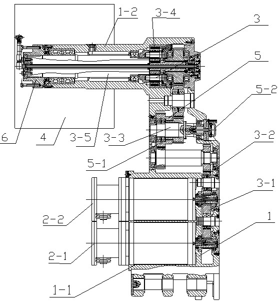
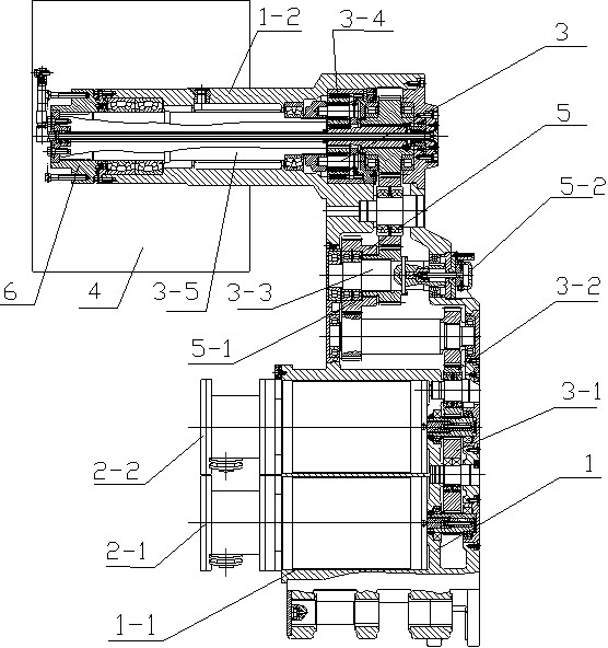
[0010] The cutting part of the double-motor U-shaped thin coal seam shearer of the present invention is mainly composed of a rocker arm housing 1, a first cutting motor 2-1, a second cutting motor 2-2, a rocking arm reduction box 3, and a cutting drum 4, the rocker arm housing 1 includes a motor installation cavity 1-1 and a rocker arm reducer output shaft installation cavity 1-2 arranged in parallel, the output shaft installation cavity 1-2 of the rocker arm reducer is elongated, The length of the slender rocker reducer output shaft installation chamber 1-2 is 830mm, and the outer diameter is 350mm. The motor installation chamber 1-1 is on the same side as the rocker arm reducer output shaft installation chamber 1-2, and the outline forms a U shape; the first cutting motor 2-1 and the second cutting motor 2-2 are installed side by side on the In th...


PUM

PropertyMeasurementUnit
Lengthaaaaaaaaaa
Outer diameteraaaaaaaaaa

Abstract

A double-motor U-shaped cutting portion of a thin seam mining machine comprises a rocker arm casing, two cutting motors, a rocker arm reduction gearbox and a cutting roller. A motor installing cavity of the rocker arm casing and an extending end of the rocker arm casing are on the same side, and the contour of the motor installing cavity and the contour of extending end of the rocker arm casing are in a U shape, and the extending end of the rocker arm casing is elongated. The rocker arm reduction gearbox comprises a clutch, a third-stage idle gear, a fourth-stage cylindrical gear and a planetary gear mechanism, the clutch is arranged on a third-stage cutting shaft group of a transmission chain, the planetary gear mechanism is arranged at the tail end of the transmission chain, the two cutting motors transmit power to the rocker arm reduction gearbox through a first idle gear and a second idle gear, the power is transmitted to the cutting roller after speed reduction through the fourth-stage cylindrical gear and the planetary gear mechanism, an involute spline of the third-stage cutting shaft group of the transmission chain is disconnected by pulling a clutch handle, and the transmission chain is cut off so as to avoid accidents during overhaul. The cutting portion is large in installed power, strong in mining capability, good in coal charging effect, safe and reliable, and a large cutting deep roller can be installed to develop a hard-coal working surface.

Description

technical field [0001] The invention relates to a cutting part of a coal shearer, in particular to a double-motor U-shaped thin coal seam shearer cutting part suitable for large cutting depth in thin coal seam coal mines and hard coal working faces. Background technique [0002] With the surge of demand for coal and the reduction of exploitable coal resources in our country, more and more attention has been paid to the mining of thin coal seams. However, there are currently two problems in the technology of the cutting section of the drum-type thin coal seam shearer: first, the installed power of the cutting section is generally low, and it is difficult to cut hard coal; second, the coal loading effect of the drum is not good, Cut depth is small. The reasons for these problems are: first, the thin coal seam working face requires that the height of the fuselage should not be too high and in order not to affect the coal passing, the size of the motor is limited,...

Claims


Application Information

Patent Timeline
IPC IPC(8): E21C25/06H02P6/04
Inventor 刘送永袁野江红祥崔新霞付林高魁东
Owner CHINA UNIV OF MINING & TECH
Learn More