Connecting rod sliding shoe type flow distribution radial plunger pump

A radial column and sliding shoe technology, applied in the direction of variable displacement pump components, components of pumping devices for elastic fluids, pumps, etc. Pump leakage and other problems, to achieve the effect of improving work efficiency, sensitive and reliable oil control, and prolonging service life

Inactive Publication Date: 2012-08-22
吕慧彬
View PDF10 Cites 8 Cited by
  • Summary
  • Abstract
  • Description
  • Claims
  • Application Information

AI Technical Summary

Problems solved by technology

Due to the large radial force on the distribution shaft of the radial piston pump with shaft distribution, the phenomenon of eccentric wear and shaft holding on the distribution shaft occurs.
In addition, the worn gap between the distribution shaft and the bushing cannot be automatically compensated, resulting in a large leakage of the radial piston pump. These reasons limit the further improvement of the speed and rated pressure of the radial piston pump
The radial piston pump with valve distribution often causes failure due to the inertia of the valve and the movement of the plunger.
For example, when the plunger is switched from the oil suction process to the oil pressure process, when the plunger has started to move upwards, the action of the valve will lag behind the action of the plunger due to the inertia of the valve. The valve has not opened, which will cause the plunger to press the oil into the suction chamber

Method used


Image

  • Connecting rod sliding shoe type flow distribution radial plunger pump
  • Connecting rod sliding shoe type flow distribution radial plunger pump
  • Connecting rod sliding shoe type flow distribution radial plunger pump

Examples


Embodiment Construction

[0023] The specific implementation manner of the present invention will be further described below in conjunction with the accompanying drawings.

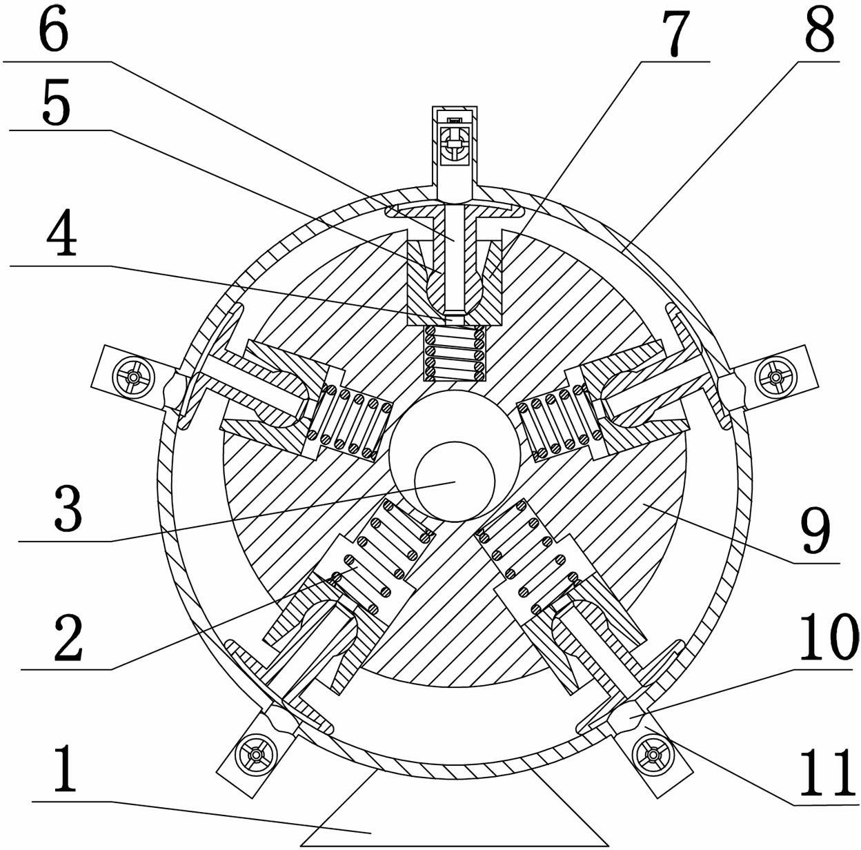
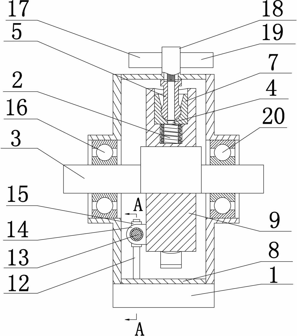
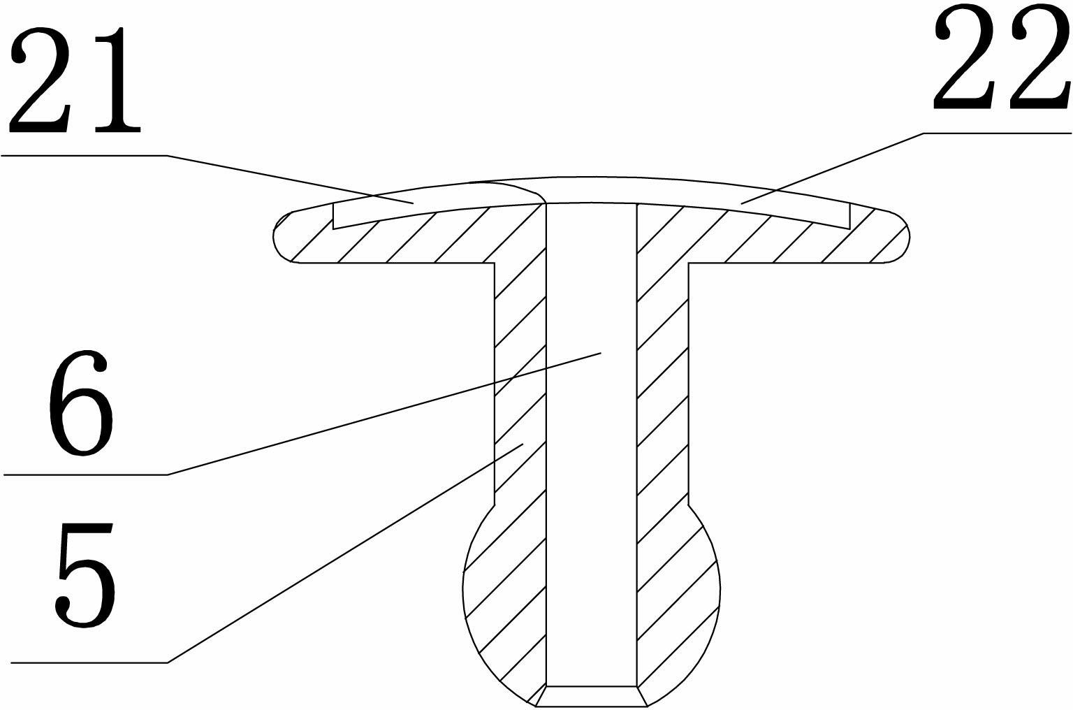
[0024] Such as figure 1 , 2 As shown, a connecting rod sliding shoe type flow distribution radial piston pump includes an eccentric shaft 3, a stator 8, a rotor 9, a set of plungers 7 with a central oil hole 4, a set of connecting rod sliding shoes 5, a The group oil control valve 11 is characterized in that the bottom of the stator 8 is fixedly connected with the base 1, the front and rear of the stator 8 are respectively provided with a front bearing assembly 20 and a rear bearing assembly 16, and the inner wall of the stator 8 A group of stator oil holes 10 are evenly distributed in the radial direction, and the group of stator oil holes 10 are connected to the group of oil control valves 11 correspondingly, and the eccentric shaft 3 is arranged in the stator 8 with two ends Connected with the front bearing assembly 20 and the...


PUM


Abstract

The invention discloses a connecting rod sliding shoe type flow distribution radial plunger pump, which comprises an eccentric shaft, a stator, a rotor, plungers, connecting rod sliding shoes and oil control valves and is characterized in that the bottom of the stator is fixedly connected with a base. A group of stator oil holes are evenly distributed on the inner wall of the stator along the radial direction, the group of stator oil holes are correspondingly connected with a group of oil control valves, the eccentric shaft is arranged in the stator, the rotor is arranged in the stator and connected to the outer side of the eccentric shaft in sleeved mode, a rotor anti-rotation mechanism is arranged at the bottom of the rotor, a group of plunger holes are evenly distributed on the rotor along the radial direction, a group of plungers are respectively arranged in the group of plunger holes, plunger return springs are arranged between the bottoms of the plunger holes and the plungers, the tops of a group of connecting rod sliding shoes are respectively arranged in the group of plungers and hinged to a group of plunger balls, and the bottoms of the group of connecting rod sliding shoes are slidingly connected with the inner wall of the stator and corresponds to the group of stator oil holes. The connecting rod sliding shoe type flow distribution radial plunger pump is sensitive and reliable in oil distribution, small in hydraulic oil leakage, low in fault rate and capable of effectively overcoming defects of a flow distribution mode of an existing radial plunger pump.

Description

technical field [0001] The invention belongs to the technical field of radial plunger pumps, in particular to a connecting rod sliding shoe type radial plunger pump with flow distribution. Background technique [0002] The plunger pump is an important device of the hydraulic system. It relies on the reciprocating movement of the plunger in the cylinder to change the volume of the sealed working chamber to realize oil suction and pressure. The plunger pump has the advantages of high rated pressure, compact structure, high efficiency and convenient flow adjustment, and is widely used in high pressure, large flow and flow adjustment occasions, such as hydraulic presses, engineering machinery and ships. As a type of plunger pump, the radial piston pump is a plunger pump in which the reciprocating direction of the piston or plunger is perpendicular to the drive shaft. Radial piston pump consists of stator, rotor, connecting rod shoe, plunger, flow distribution mechanism and so o...

Claims


Application Information

Patent Timeline
Patent Type & Authority Applications(China)
IPC IPC(8): F04B1/047F04B53/00F04B53/10
Inventor 吕慧彬
Owner 吕慧彬
Why Eureka
Try Eureka