Composite rotor in heat exchange tube

A technology of heat exchange tubes and internal compounding, applied in the direction of heat transfer modification, heat exchange equipment, rotating equipment cleaning, etc., can solve the problems of energy waste, heat transfer performance decline, pipeline transportation resistance increase, etc., to achieve enhanced mixing and disturbance , increase the disturbance effect, improve the effect of heat transfer efficiency

Active Publication Date: 2012-08-22
BEIJING UNIV OF CHEM TECH
View PDF8 Cites 4 Cited by
  • Summary
  • Abstract
  • Description
  • Claims
  • Application Information

AI Technical Summary

Problems solved by technology

[0002] With the continuous progress of society in the 21st century, energy saving and emission reduction in today's society is a key technology that the world attaches great importance to, especially in petroleum, chemical, thermal power, nuclear power, metallurgy, light industry, aviation devices and ship vehicles, etc. Many heat exchangers are applied in many fields, among which the shell-and-tube heat exchanger is the most widely used, but the inner wall of these heat exchange tubes generally has layered dirt, which leads to an increase in the resistance of fluid transport in the pipeline, and in severe cases It will block the pipe, and the heat transfer performance will be greatly reduced at the same time; the dirt in the heat exchange tube will seriously reduce the heat transfer efficiency and cause major energy waste. At the same time, the dirt is generally corrosive, and the pipe wall will be corroded.
The above rotors all rotate around the center of the heat exchange tube, so the fluid in the tube cannot be sufficiently disturbed

Method used


Image

  • Composite rotor in heat exchange tube
  • Composite rotor in heat exchange tube
  • Composite rotor in heat exchange tube

Examples


Embodiment Construction

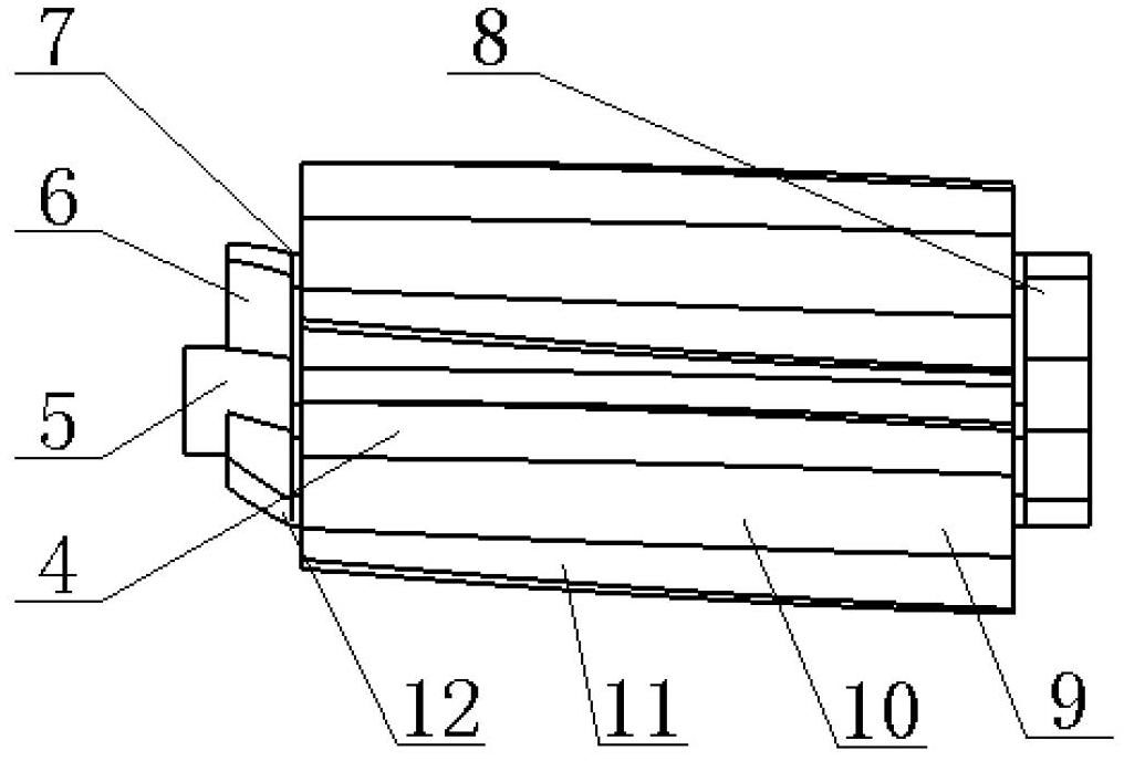
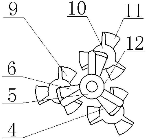
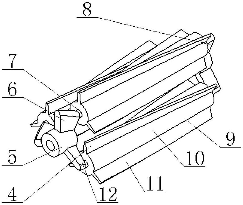
[0020] Such as Figure 6 and Figure 7 As shown, an implementation example of a composite rotor in a heat exchange tube according to the present invention includes a rotating shaft 1, a stopper 2, a hanging piece 3 and a composite rotor 4, and the hanging piece 3 is mounted on the rotating shaft 1, Several composite rotors 4 are mounted on the rotating shaft 1. The composite rotor 4 is composed of a main rotor 12 and a planetary rotor 9. The main rotor 12 includes a main rotor hollow shaft 5, a drive rod 6, a planetary shaft 7 and a tail rod 8. Partly, the planetary rotor 9 is composed of a planetary rotor hollow shaft 10 and blades 11 , and the two ends of the pendant 3 are axially fixed by the limiter 2 .

[0021] Such as Figure 1 to Figure 7 , figure 1 is the front view of the composite rotor 4, figure 2 for figure 1 left view of image 3 yes figure 1 3D view of the Figure 4 is a three-dimensional view of the main rotor 12, Figure 5 is a three-dimensional view ...


PUM


Abstract

The invention provides a composite rotor in a heat exchange tube, which is composed of a main rotor and a planet rotor, wherein the main rotor comprises a main rotor hollow shaft, a drive rod, a planet shaft and a tail rod, the drive rod and the tail rod are composed of a plurality of short blades respectively, an angle is formed between the short blades and an axis of the main rotor hollow shaft, the planet shaft is composed of a planet rotor hollow shaft and blades, a certain angle is formed between the blades of the planet rotor and a central line of the planet rotor hollow shaft, the planet rotor hollow shaft is sleeved on the planet shaft of the main rotor, and then the tail rod is connected to the end portions of the main rotor hollow shaft and the planet shaft. According to the composite rotor in the heat exchange tube, the drive rod is pushed by a fluid to provide a driving force for the main rotor to rotate, simultaneously with a rotation of the main rotor, the planet rotor obtains a rotation angular velocity which is around the center of the heat exchange tube, so that a rotary speed of the rotor can be reduced, and the range and degree of a mixing and a disturbance of the fluid are enhanced; and the planet rotor can obtain an angular velocity rotating around the planet shaft, and the disturbance of the fluid in an area close to tube wall is further increased.

Description

technical field [0001] The invention relates to an interpolation element for enhancing heat transfer and antifouling and decontamination in heat exchange tubes of equipment such as shell and tube heat exchangers and heat exchange reactors. Background technique [0002] With the continuous progress of society in the 21st century, energy saving and emission reduction in today's society is a key technology that the world attaches great importance to, especially in petroleum, chemical, thermal power, nuclear power, metallurgy, light industry, aviation devices and ship vehicles, etc. Many heat exchangers are applied in many fields, among which the shell-and-tube heat exchanger is the most widely used, but the inner wall of these heat exchange tubes generally has layered dirt, which leads to an increase in the resistance of fluid transport in the pipeline, and in severe cases It will block the pipe, and the heat transfer performance will be greatly reduced at the same time; the di...

Claims


Application Information

Patent Timeline
Patent Type & Authority Applications(China)
IPC IPC(8): F28F13/12F28G3/00
Inventor 杨卫民姜鹏阎华张震丁玉梅
Owner BEIJING UNIV OF CHEM TECH
Why Eureka
Try Eureka