Combined switch and synchronous rectification circuit

A combined switch and switch technology, applied in the field of power supply, can solve the problems of large diode conduction loss, large reverse recovery loss, and inability to ensure current flow through external parallel diodes, etc., to achieve reduced conduction loss, low conduction resistance, Eliminates the effect of reverse recovery loss

Inactive Publication Date: 2012-08-22
EMERSON NETWORK POWER ENERGY SYST NORTH AMERICA
View PDF4 Cites 19 Cited by
  • Summary
  • Abstract
  • Description
  • Claims
  • Application Information

AI Technical Summary

Problems solved by technology

[0005] In view of this, the technical problem to be solved by the present invention is to provide a combined switch, which can solve the problems of large diode conduction loss in ordinary rectification and large reverse recovery loss when using MOSFET and its body diode for synchronous rectification; and When using MOSFET external parallel diode synchronous rectification, the current cannot be guaranteed to flow through the external parallel diode, which improves the efficiency of the circuit

Method used


Image

  • Combined switch and synchronous rectification circuit
  • Combined switch and synchronous rectification circuit
  • Combined switch and synchronous rectification circuit

Examples


Embodiment Construction

[0048] Hereinafter, the realization of the combined switch in the embodiment of the present invention will be described in detail in conjunction with the accompanying drawings; and the realization of the synchronous rectification circuit using the combined switch will be described accordingly.

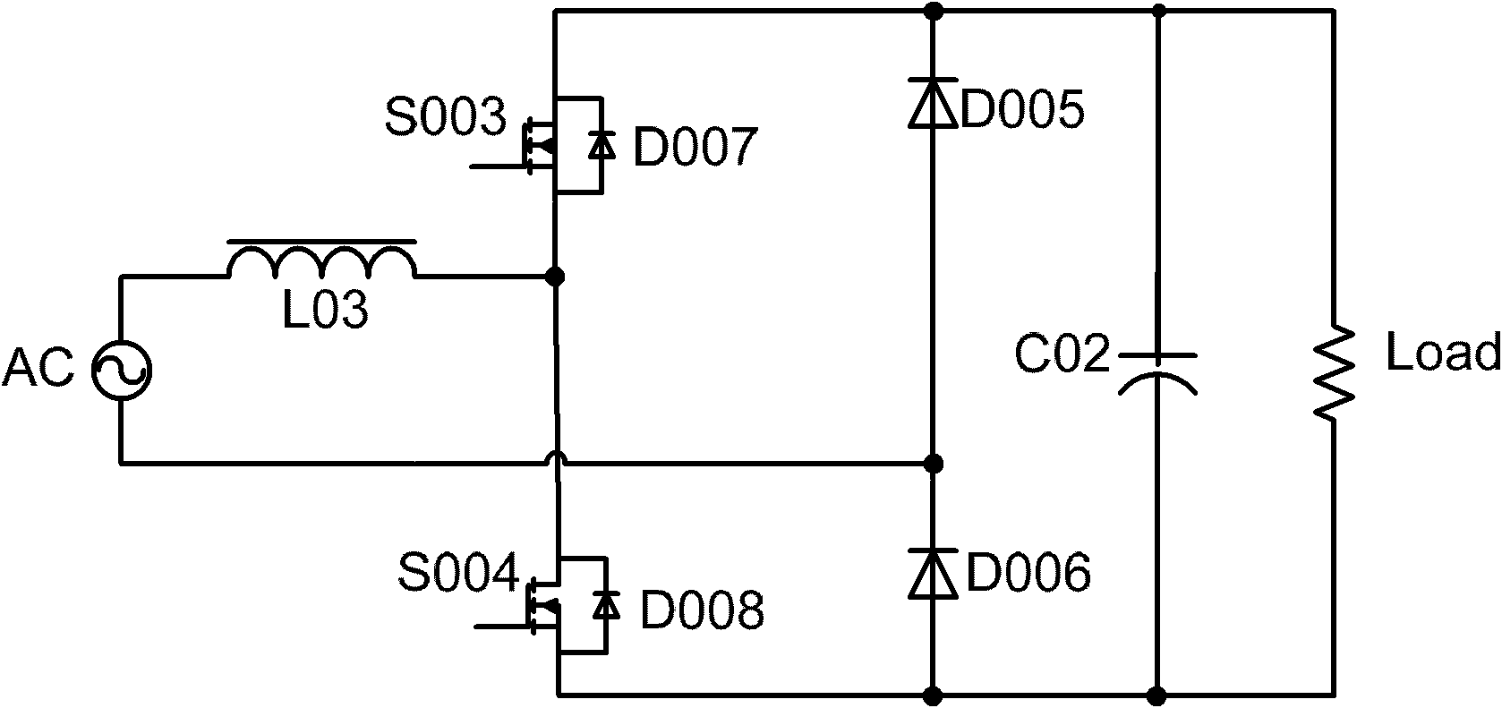
[0049] First, the applicant briefly explained the body diode of the MOSFET: there is a parasitic diode between the source and drain of the MOSFET, such as figure 2 The diode D007 corresponding to the MOSFET S003, etc., this parasitic diode is called the body diode of the MOSFET. In the embodiment of the present invention, the body diode and its corresponding MOSFET are described separately.

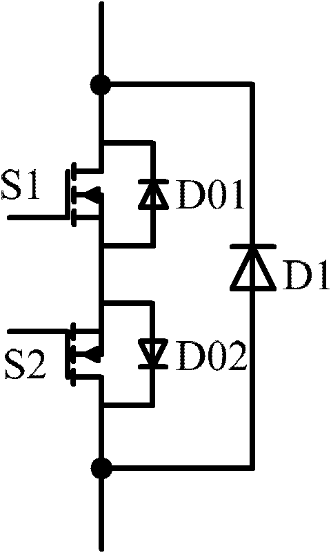
[0050] The combined switch according to the embodiment of the present invention includes: a first transistor, a second transistor, a first body diode, a second body diode, and a first diode; wherein,

[0051] The cathode of the first body diode is connected to the drain of the first transistor, ...


PUM


Abstract

The invention discloses a combined switch comprising a first transistor, a second transistor, a first body diode, a second body diode and a first diode, wherein the cathode of the first body diode is connected with the drain of the first transistor, and the anode of the first body diode is connected with the source of the first transistor; and the cathode of the second body diode is connected with the drain of the second transistor, and the anode of the second body diode is connected with the source of the second transistor. The combined switch further comprises a first transistor and a second transistor both of which are reversely connected in series, wherein the first diode is parallelly connected with the first transistor and the second transistor which are connected in series. The combined switch can be used for solving the problems that a diode has large conduction loss during normal rectification, or the reverse recovery losses of body diodes are large by utilizing an MOSFET (metal oxide semiconductor field effect transistor) and the body diodes during synchronous rectification and the like, and improving the efficiency of a circuit.

Description

technical field [0001] The invention relates to the field of power supplies, in particular to a combination switch and a synchronous rectification circuit. Background technique [0002] With the introduction of the concept of green energy, people's awareness of environmental protection and energy saving is getting stronger and stronger, and all fields are trying to reduce losses and improve efficiency, and the power supply field is no exception. Nowadays, the requirements for power supply efficiency are getting higher and higher, and the conduction loss of the rectifier diode and the loss caused by reverse recovery account for a large proportion of the loss of the power supply. For a long time, a large number of engineers have invested a lot of energy, using various methods to reduce the loss of rectifier diodes, and are committed to optimizing the working performance of rectifier diodes. [0003] figure 1 Shown is an ordinary bridgeless power factor correction (Power Fact...

Claims


Application Information

Patent Timeline
IPC IPC(8): H02M7/162
CPCH02M7/217
Inventor 王琳化黄立巍弗兰克·赫尔特
Owner EMERSON NETWORK POWER ENERGY SYST NORTH AMERICA
Why Eureka
Try Eureka