A high-efficiency high-gain converter and its control method

A high-gain, converter technology, applied in the direction of converting DC power input to DC power output, control/regulation systems, output power conversion devices, etc. Achieve the effect of fewer power tubes, higher switching frequency and lower voltage stress

Active Publication Date: 2021-11-12
NANTONG UNIVERSITY
View PDF6 Cites 0 Cited by
  • Summary
  • Abstract
  • Description
  • Claims
  • Application Information

AI Technical Summary

Problems solved by technology

However, like the switched inductor Boost converter, the power device bears high voltage stress (equal to the output voltage), and the switching loss is relatively large
Since high-voltage power devices have larger on-state voltage drop (or on-state resistance) and higher prices, their on-state loss and cost are higher and their efficiency is lower.
In addition, the above solutions generally have multiple filter elements, and the volume of the converter is large, which is difficult to meet the technical requirements of the small volume of photovoltaic DC modules
Increasing the switching frequency can effectively reduce the volume and weight of the filter components, but the switching loss increases significantly, and the system efficiency drops seriously

Method used


Image

  • A high-efficiency high-gain converter and its control method
  • A high-efficiency high-gain converter and its control method
  • A high-efficiency high-gain converter and its control method

Examples


Embodiment Construction

[0036] The following will clearly and completely describe the technical solutions in the embodiments of the present application with reference to the accompanying drawings in the embodiments of the present application. Obviously, the described embodiments are only part of the embodiments of the present application, not all of them. Based on the embodiments in this application, all other embodiments obtained by persons of ordinary skill in the art without making creative efforts fall within the protection scope of the present invention.

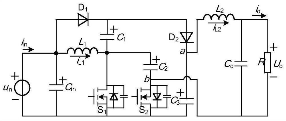
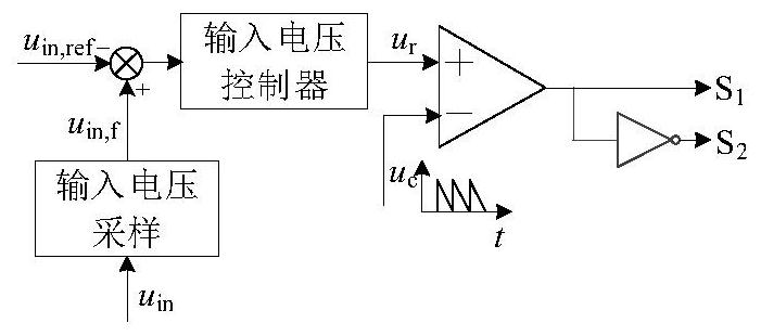
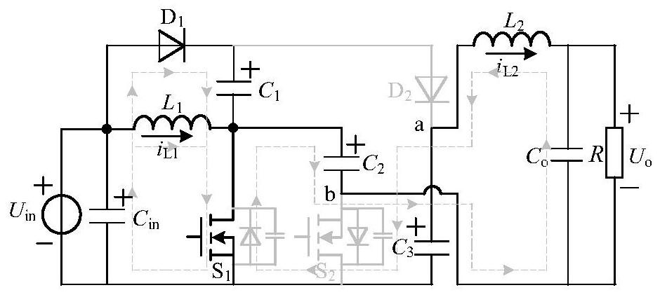
[0037] The invention provides a high-efficiency high-gain converter, the circuit structure is as figure 1 shown. The high-efficiency high-gain converter includes a DC power supply U in , Input filter capacitor C in , the first capacitance C 1 , the second capacitance C 2 , the third capacitor C 3 , the first inductance L 1 , the second inductance L 2 , the first switch tube S 1 , the second switch tube S 2 , the first diode D 1 , the...


PUM


Abstract

The invention belongs to the technical field of DC-DC converters, and discloses a high-efficiency high-gain converter and a control method thereof. Anode connection; the other end of the first inductor is connected to the drain of the first switching tube, the negative pole of the first capacitor, and the positive pole of the second capacitor; the cathode of the first diode is connected to the positive pole of the first capacitor and the second diode The anode of the second capacitor is connected; the negative pole of the second capacitor is connected to the source of the second switching tube, the negative pole of the output filter capacitor, and one end of the DC load; the cathode of the second diode is connected to one end of the second inductor and the positive pole of the third capacitor ; The other end of the second inductance is connected to the positive pole of the output filter capacitor and the other end of the DC load; the negative pole of the DC power supply is connected to the negative pole of the third capacitor, the source pole of the first switching tube, the drain pole of the second switching tube, and the input filter The negative terminal connection of the capacitor; it has the characteristics of high voltage gain, high efficiency, low voltage stress and small size.

Description

technical field [0001] The invention belongs to the technical field of DC-DC step-up converters, and in particular relates to a high-efficiency high-gain converter and a control method thereof. Background technique [0002] The DC module distributed photovoltaic grid-connected power generation system can realize maximum power point tracking control at the module level, has strong anti-local shadowing ability, and is easy to standardize production and install flexibly. However, due to the low terminal voltage of its input power supply (composed of a single or two photovoltaic modules in series), the photovoltaic DC module must have a high voltage gain (G=U o / U in ), to meet the DC bus voltage requirements of the subsequent grid-connected inverter. In addition, in order to reduce costs, facilitate installation, and further improve solar energy utilization, photovoltaic DC modules also need to have the characteristics of a small number of components, small size, and high con...

Claims


Application Information

Patent Timeline
Patent Type & Authority Patents(China)
IPC IPC(8): H02M3/158
CPCH02M3/158
Inventor 秦岭许兴钱天泓田民周磊段冰莹沈家鹏高娟刘宇涵
Owner NANTONG UNIVERSITY
Why Eureka
Try Eureka