Intermediate current mode dual-tube forward micro-inverter and its digital control device

A dual-tube forward excitation, micro-inverter technology, applied in the direction of adjusting electrical variables, control/regulating systems, output power conversion devices, etc., can solve the problem that boost converters are difficult to achieve high boost ratio, efficiency is difficult, and high efficiency and other problems to achieve the effect of eliminating reverse recovery loss

Active Publication Date: 2018-08-10
东台城东科技创业园管理有限公司
View PDF4 Cites 0 Cited by
  • Summary
  • Abstract
  • Description
  • Claims
  • Application Information

AI Technical Summary

Problems solved by technology

[0005] The output voltage of a single photovoltaic cell is relatively low (25V-50V). To achieve grid connection, a two-stage circuit structure can be used, and then invert after boosting. The commonly used boost converter is difficult to achieve a high boost ratio, so it is necessary to A high boost ratio converter with a specific structure, this type of converter generally uses the adjustment of the turn ratio of the coupled inductor to achieve a boost ratio of more than 10 times, but the high boost ratio converter also requires more diodes and passive components. However, micro-inverters that use high-frequency transformers to achieve electrical isolation can complete the inversion function with fewer power conversion stages. At present, the most researched micro-inverters without DC links are flyback micro-inverters. In addition, forward, push-pull, full-bridge and Zeta micro-inverters have also been researched. The circuit structure of isolated full-bridge and Zeta micro-inverters is more complicated, which is not conducive to the improvement of circuit efficiency. Flyback and forward micro-inverters The circuit structure of the inverter is relatively simple, but the diode in the secondary circuit of the forward micro-inverter commutates at the peak current, which causes parasitic oscillation and reverse recovery loss of the diode, and it is difficult to improve the efficiency; the flyback micro-inverter The power is limited by the energy storage transformer. As the power of a single photovoltaic cell increases, its efficiency is difficult to achieve high efficiency when the power is high. Therefore, interleaved flyback micro-inverters have been widely used in recent years, but the rear stage must increase the reverse inverter. inverter, which increases the complexity of the microinverter

Method used


Image

  • Intermediate current mode dual-tube forward micro-inverter and its digital control device
  • Intermediate current mode dual-tube forward micro-inverter and its digital control device
  • Intermediate current mode dual-tube forward micro-inverter and its digital control device

Examples


Embodiment Construction

[0031] Below in conjunction with specific embodiment, further illustrate the present invention, should be understood that these embodiments are only used to illustrate the present invention and are not intended to limit the scope of the present invention, after having read the present invention, those skilled in the art will understand various equivalent forms of the present invention All modifications fall within the scope defined by the appended claims of the present application.

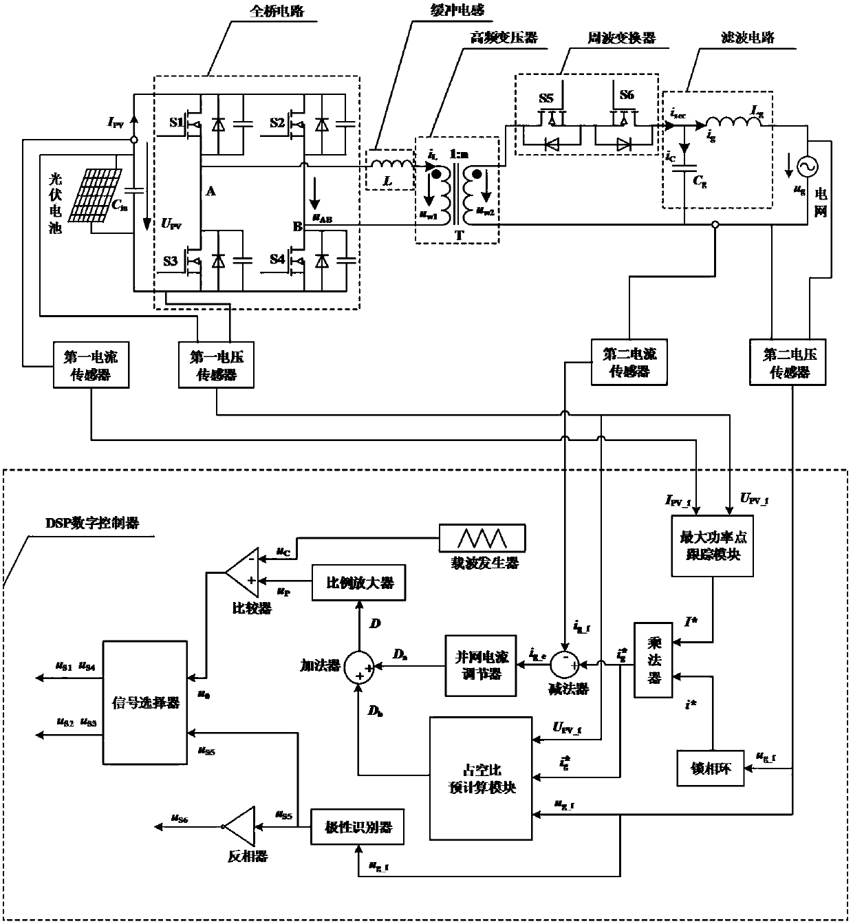
[0032] Such as figure 1 As shown, the middle current type dual-tube forward micro-inverter, including the input filter capacitor C in , full-bridge circuit, snubber inductor L, high-frequency transformer T, cycloconverter and LC grid-connected filter circuit, the following will describe their interconnection and components in detail.

[0033] The full bridge circuit uses photovoltaic cells as the input power supply, and includes the first switching tube S1, the second switching tube S2, the third...


PUM


Abstract

The invention discloses an intermediate current type double-tube forward micro-inverter and its digital control device. The intermediate current type double-tube forward micro-inverter includes an input filter capacitor, a full-bridge circuit, a buffer inductor, a high-frequency transformer, a cycle Converter, grid-connected filter circuit. The digital control device includes a first voltage sensor, a second voltage sensor, a first current sensor, a second current sensor and a DSP digital controller. In the full-bridge circuit, only two switches in the same stage can transfer the output energy of the photovoltaic cell to the secondary side of the transformer, which reduces the loss of the switching device; the intermediate current type dual-tube forward micro-inverter uses the transformer The leakage inductance realizes that all switches work in a soft switching state, and eliminates the reverse recovery loss of the rectifier diode on the secondary side of the transformer, improving the performance and efficiency of the micro-inverter.

Description

technical field [0001] The invention relates to an intermediate current type double-tube forward micro-inverter and a digital control device thereof, and belongs to the technical field of power electronic converters and control thereof. Background technique [0002] The non-renewable and high-pollution characteristics of conventional fossil energy require the government to re-examine the existing energy policy, and a series of policies and regulations to encourage the use of renewable energy have been introduced one after another. Among them, photovoltaic power generation has achieved rapid development. With the continuous reduction in the price of photovoltaic cells and the introduction of relevant favorable policies, more and more units and individuals have shown great interest in photovoltaic power generation. [0003] A development trend of photovoltaic power generation is modular power supply, which can ensure that each photovoltaic cell works at the maximum power poin...

Claims


Application Information

Patent Timeline
Patent Type & Authority Patents(China)
IPC IPC(8): H02M3/335
CPCH02M3/3353H02M1/0058Y02B70/10Y02E10/56
Inventor 吴云亚阚加荣梁艳商志根冯赛非薛迎成姚志垒
Owner 东台城东科技创业园管理有限公司
Why Eureka
Try Eureka