Flow-rate regulator, flow-rate-regulating set, and method for regulating the flow-rate of intravenous fluid

A technology of flow regulating device and flow regulator, which is applied in the direction of measuring device, flow control, control/regulation system, etc., which can solve problems such as the movement of difficult-to-operate parts, troublesome operation, and medical accidents, so as to improve operating efficiency and adjust speed Quickly and quickly adjust the flow effect

Inactive Publication Date: 2012-08-29
HANVIT MD +1
View PDF8 Cites 5 Cited by
  • Summary
  • Abstract
  • Description
  • Claims
  • Application Information

AI Technical Summary

Problems solved by technology

[0009] When the infusion flow is adjusted according to the prescribed flow after the infusion device is installed, if the user fully believes in the accuracy of the flow adjustment function of the intravenous injection flow regulator, then sometimes they will mistakenly believe that the prescribed flow has been reached, resulting in medical accidents
In addition, after the user adjusts the operation part according to the value 15e of the prescribed flow rate, even if the input flow rate is found to be inconsistent with the prescribed flow rate by measuring the flow rate, it is difficult to accurately judge the specific movement amount of the operation part, so it has to be adjusted bit by bit. Move the adjustment part to measure the flow rate repeatedly
[0010] Korean No. 10-0706954 patent "Infusion Infusion Speed ​​Measuring Device" and Korean No. 10-0872089 Patent "Infusion Infusion Auxiliary Device" invented by the inventor, although easy to carry, and can quickly and easily adjust the infusion flow , however, it is necessary to repeatedly operate the operation part 15a of the infusion flow regulator 15 until the dripping cycle of the liquid drops coincides with the sound cycle
As mentioned above, the existing infusion flow regulators all have disadvantages such as troublesome operation and need to go through several operations to achieve accurate flow.

Method used


Image

  • Flow-rate regulator, flow-rate-regulating set, and method for regulating the flow-rate of intravenous fluid
  • Flow-rate regulator, flow-rate-regulating set, and method for regulating the flow-rate of intravenous fluid
  • Flow-rate regulator, flow-rate-regulating set, and method for regulating the flow-rate of intravenous fluid

Examples


Embodiment Construction

[0047] Embodiments of the present invention will be described in detail below in conjunction with the accompanying drawings, so that those skilled in the art can easily implement. In the drawings, the same symbols are assigned to components with the same structure or the same function. When describing the present invention, if the detailed description of known related functions or known structures affects the description of the present invention, the detailed description will be omitted.

[0048] Infusion flow regulator:

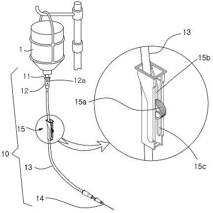
[0049] image 3 It is a structural schematic diagram of the first embodiment of the infusion flow regulator 100 of the present invention. That is, it is a schematic diagram of the structure when the present invention is applied to an IV Flow Regulator type infusion flow regulator.

[0050] The IV Flow Regulator (IV Flow Regulator) type infusion flow regulator is a known technology. A brief description of its structure is as follows: the body 140 is equip...


PUM


Abstract

The prevent invention relates to a flow rate regulator which utilizes a manipulating unit to change a connection pipe diameter of a flow device so as to regulate flow passing the connection pipe. A reference point is defined in the manipulating range of a manipulating part for regulating a flow rate of the intravenous fluid so as to match a manipulation point of the manipulating part with a flow rate measured at a reference point with respect to a prescribed flow rate to be injected, thereby regulating the prescribed flow rate. The flow rate regulator has the advantages of a fast regulating speed, high accuracy and high efficiency and can avoid measuring errors and further avoid medical negligence.

Description

technical field [0001] The invention relates to a transfusion flow regulator, a transfusion flow regulating device and a transfusion flow regulating method which can quickly and accurately adjust the transfusion flow to the prescribed flow. Background technique [0002] Such as figure 1 As shown, the intravenous infusion device (IV) for directly injecting the injection into the vein consists of an infusion bottle 1 containing the injection, and a bottle insertion needle 11 inserted into the airtight cover of the infusion bottle and capable of dripping the infusion, fixed on the The lower end of the insertion needle 11 can make the injection solution drip in the form of droplets (12a, drop, unit: gtt) into the drip chamber (Drip Chamber) 12, insert the infusion needle 14 into the vein, and connect the drip chamber 12 and the infusion The needle 14, the connecting tube 13 as the infusion channel, and the infusion flow regulator 15 which is arranged in the middle of the infusi...

Claims


Application Information

Patent Timeline
Patent Type & Authority Applications(China)
IPC IPC(8): A61M5/175A61M5/168G01D13/02G06Q50/06
CPCA61M5/16813A61M39/285A61M39/286A61M5/168G01D13/02G06Q50/06
Inventor 李斗镛
Owner HANVIT MD
Why Eureka
Try Eureka