Design of wheel leg type moving foot of multi-joint chain link type robot

A multi-joint, robot technology, applied in the direction of motor vehicles, transportation and packaging, etc., can solve the problems of strong anti-disturbance ability, high bearing capacity, wide reachable area of ​​the foot end, etc., to achieve the effect of increasing torque and improving service life

Inactive Publication Date: 2012-08-29
BEIJING INSTITUTE OF TECHNOLOGYGY
View PDF5 Cites 23 Cited by
  • Summary
  • Abstract
  • Description
  • Claims
  • Application Information

AI Technical Summary

Problems solved by technology

Although their sports foot design has the characteristics of compact structure, it lacks the charac

Method used


Image

  • Design of wheel leg type moving foot of multi-joint chain link type robot
  • Design of wheel leg type moving foot of multi-joint chain link type robot
  • Design of wheel leg type moving foot of multi-joint chain link type robot

Examples


Embodiment Construction

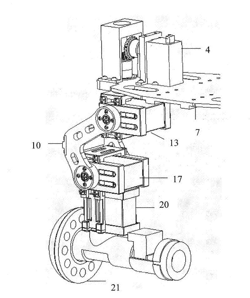
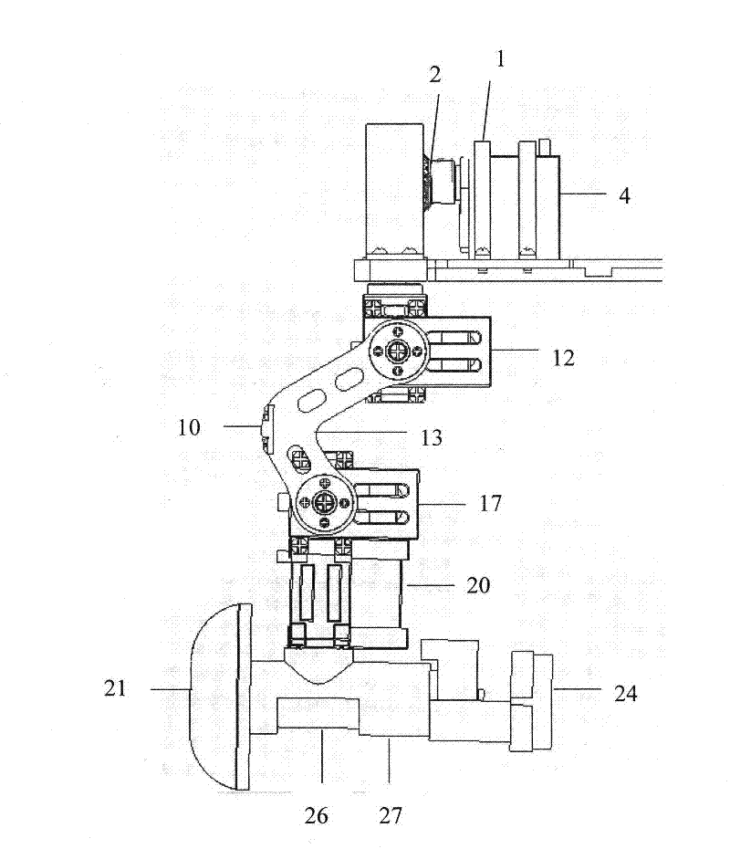
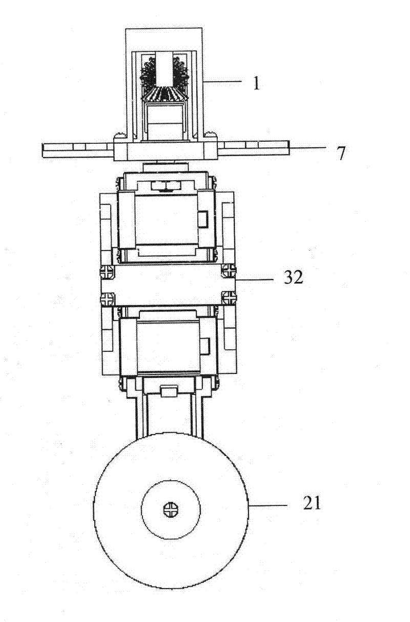
[0021] Such as figure 1 As shown, it is a schematic diagram of the single foot design of the wheel-legged sports foot of the multi-joint chain-link robot, including the No. 1 steering gear on the upper part of the connecting plate, the No. 2, No. 3, and No. motor. The surrounding structure of the steering gear includes: the bracket one (1) of the No. 1 steering gear (4) fixed by screws, the bevel gear (2), the bearing (3), the No. 1 shaft (6) and the bracket for connecting with the lower structure. The connection plate (7), the combination of the above mechanisms realizes the conversion of the horizontal rotation motion of the No. 1 steering gear into a vertical rotation motion. The No. 2 steering gear (13) is fixedly connected with four steering gear support frames by screws to realize the vertical rotation of the crank arm joint. No. 3 steering gear (17) is fixedly connected with four steering gear support frames by screws to realize the vertical rotation of the crank arm ...


PUM


Abstract

The invention relates to a design of a wheel leg type moving foot of a multi-joint chain link type robot based on modularization. In system composition, the moving foot and a robot body are in an open chain structure relationship and totally have five active degrees of freedom, and each active degree of freedom can be completed by the driving of a steering engine or direct current servo motor. In structural design, the moving foot is in a crank arm structure, and is provided with four rotational joints and one wheel foot. By the front crank arm and rear crank arm of the leg and the wheel type design of the moving foot, the multi-joint chain link type robot has the advantages of good geography adaptability of a leg-type robot and strong mobility of a wheel-type robot, and a landing end of the moving foot can be landed in any position in a three-dimensional space of a reachable area of the moving foot. By a bevel gear at the end part of a moving output shaft of the steering engine, radial load directly borne by a motor can be avoided, and the service life of the motor is prolonged. By the special curvature design of a bearing small wheel at the bottom of the moving foot, the bending angle of the leg when the robot moves laterally horizontally just makes the landing point of the small wheel tangential with the ground so as to realize efficient gait walking.

Description

technical field [0001] The invention belongs to the application field of bionic robots, and in particular relates to the design of a wheel-leg type moving foot of a multi-joint chain link type robot. Background technique [0002] Because bionic mobile robots involve many disciplines such as machinery, automation, information, materials, artificial intelligence, etc., and have broad application prospects, the research on bionic mobile robots has always been one of the hotspots in the field of robotics. [0003] The kinematic foot mechanism is the executive mechanism of multi-legged robot walking, and it is the key link for multi-legged robot to realize non-interference walking with various gaits. The quality of the design of the kinematic foot mechanism is directly related to whether the multi-legged robot can complete a variety of preset gaits, so there are many designs on the kinematic foot of the multi-legged robot. At present, the common sports foot mechanisms include fo...

Claims


Application Information

Patent Timeline
IPC IPC(8): B62D57/032
Inventor 罗庆生韩宝玲莫洋魏天骐吴帆赵佳馨毛明哲吴迪
Owner BEIJING INSTITUTE OF TECHNOLOGYGY
Why Eureka
Try Eureka