Bicycle power generation device with automatic clutch

An automatic clutch and generator technology, applied in the direction of automatic clutch, clutch, circuit device, etc., can solve the problems of worn tires, troublesome installation and maintenance of generator hubs, and laborious riding, and achieve stable output current and simple installation and maintenance. Effect

Inactive Publication Date: 2012-08-29
上海市南洋中学
View PDF0 Cites 0 Cited by
  • Summary
  • Abstract
  • Description
  • Claims
  • Application Information

AI Technical Summary

Problems solved by technology

[0003] In order to overcome the shortcomings of the existing bicycle power generation device that the grinding lamp will wear the tire, the installation and maintenance of the power

Method used


Image

  • Bicycle power generation device with automatic clutch
  • Bicycle power generation device with automatic clutch
  • Bicycle power generation device with automatic clutch

Examples


Example Embodiment

[0015] The present invention will be further described below with reference to the accompanying drawings and specific embodiments, but it is not intended to limit the present invention.

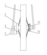
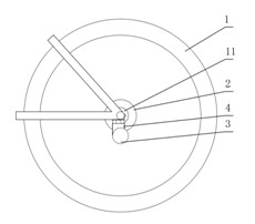
[0016] like figure 1 , figure 2 As shown, it includes a DC generator 3, a centrifugal clutch 2, the centrifugal clutch 2 is installed on the rear wheel axle 11 of the bicycle through a one-way bearing, the DC generator 3 is installed on the rear fork of the bicycle through a bracket 4, and the DC generator 3 and the centrifugal clutch 2 pass through Mechanical transmission connection. When the bicycle is riding, the sprocket 12 drives the rear wheel 1 and the rear axle 11 to rotate. At this time, the DC generator 3 does not work. When the rear axle 11 reaches a certain speed, the centrifugal clutch 2 is combined and drives the DC generator to generate electricity through mechanical transmission. Since the centrifugal clutch 2 is combined to drive the DC generator 3 to work when the rear ...


PUM


Abstract

The invention provides a bicycle power generation device with an automatic clutch, which comprises a direct current generator, and further comprises a centrifugal clutch, wherein the centrifugal clutch is mounted on the rear axle of a bicycle through a one-way bearing; and the direct current generator and the centrifugal clutch are connected with each other in a mechanical driving manner. The resistance generated by the power generation device can be offset due to the inertial force of the rotating wheels by adjusting the combined rotational speed of the centrifugal clutch, so that a rider cannot feel tired while riding the bicycle; the mounting and the maintenance are relatively simple; and a storage battery is contained, so as to ensure stable output current and further avoid abrasion on the tires of the bicycle.

Description

technical field [0001] The invention relates to a bicycle generator, in particular to a bicycle generator with an automatic clutch. Background technique [0002] Presently known bicycle power generating device has two kinds, and a kind of is a mill electric lamp, and another kind is a power generation hub. The friction wheel on the generator shaft contacts the side of the rotating bicycle rubber tire to obtain power for power generation. In this way, the side wall of the bicycle rubber tire will be worn due to the contact process between the friction wheel and the bicycle rubber tire, resulting in The safety hazard of blown tires. The dynamo hub obtains power through the relative motion between the fixed shaft and the rotating shaft of the bicycle axle. Since the dynamo hub replaces the bicycle axle, installation and maintenance are quite troublesome. During installation, the positions of all steel wires need to be readjusted. Once the parts in the hub are damaged, it is ne...

Claims


Application Information

Patent Timeline
IPC IPC(8): F03G5/02B62J6/12H02J7/32F16D43/04
Inventor 杨茜
Owner 上海市南洋中学
Why Eureka
Try Eureka