
Viscose fiber waste gas treatment control system

A waste gas treatment and control system technology, which is applied in the general control system, control/regulation system, program control, etc., can solve the problems of high operation risk, high device operation cost, and high cost, and achieve simple installation and maintenance operations and stable recovery The effect of high efficiency and recovery efficiency

Inactive Publication Date: 2012-03-28
HANGZHOU AUTOON ENVIRONMENTAL TECH CORP
View PDF0 Cites 0 Cited by
  • Summary
  • Abstract
  • Description
  • Claims
  • Application Information

AI Technical Summary

Problems solved by technology

[0004] The original waste gas treatment device control technology uses manual methods to achieve process control, and the on-site signals are mostly operators’ on-site inspections. According to the on-site instrument display records, the process control operation is complicated and the failure rate is high; it seriously affects the recovery and treatment effect; the operating cost of the entire device High; there are serious safety hazards and high energy consumption; the technical method is labor-intensive, the operation is dangerous, and the requirements for human resources and management are high, which affects the industrial application of this technology
In the original control, the process fan and process pump are directly started, which consumes a lot of energy
In addition, the control angle valve is used in the old process, and the large control angle valve is easy to leak and damage, difficult to install, operate and maintain, and high in cost

Method used


Image

  • Viscose fiber waste gas treatment control system
  • Viscose fiber waste gas treatment control system
  • Viscose fiber waste gas treatment control system

Examples


Embodiment Construction

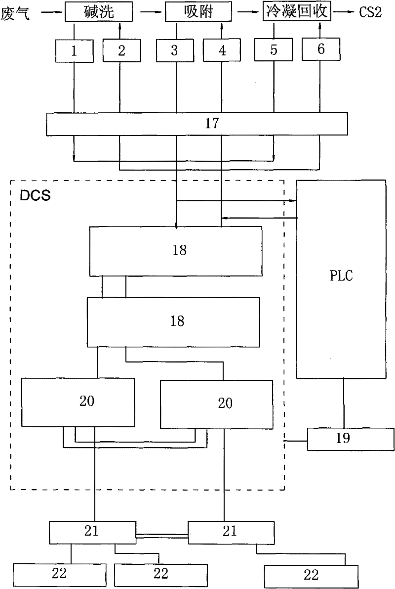
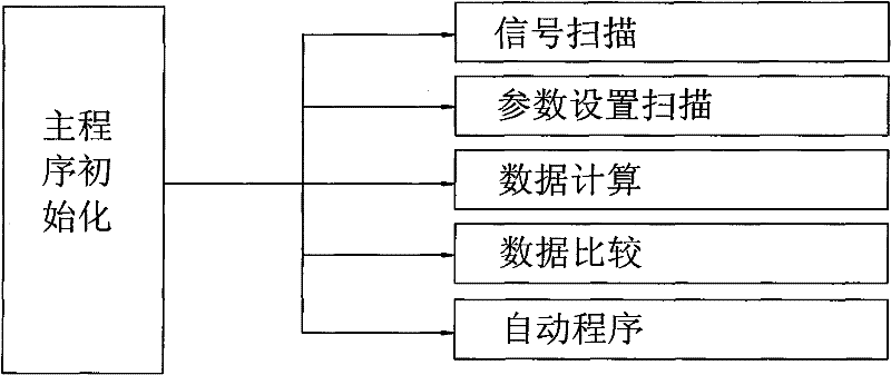
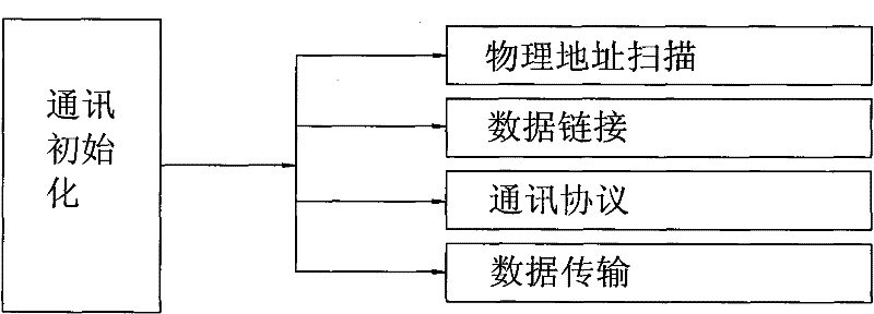
[0022] see Figure 1 to Figure 6, The invention relates to a viscose fiber waste gas treatment control system, which adopts the control idea of ​​decentralized control, centralized operation, hierarchical management, flexible configuration and convenient configuration in design. The control device mainly includes two parts: the distributed control system DCS and the programmable controller PLC. The distributed control system DCS is the main part, and the programmable controller PLC is the backup. The distributed control system DCS is equipped with two sets of redundant control modules 20, two sets of redundant switches 21, two sets of input and output modules 18 and wired communication networks for connection, which are composed of power supply, CPU, and communication modules. Adopt optical fiber communication between 20, adopt optical fiber communication between two redundant switches 21, also can set up field operation station 22 (redundant operation station, engineer statio...


PUM


Abstract

The invention discloses a viscose fiber waste gas treatment control system. A distributed control system and a programmable controller are combined together for control. The distributed control system is provided with a redundancy control module and an input and output module. The redundancy control module is connected with a redundancy switchboard. The input and output module is connected with asignal isolation and transmission device. The redundancy switchboard is connected with a field operation station. The signal isolation and transmission device is connected with an alkaline washing signal acquisition device, an adsorption signal acquisition device, a condensation signal acquisition device, an alkaline washing control switch, an adsorption control switch and a condensation control switch. A changeover switch is connected with the distributed control system and the programmable controller. The viscose fiber waste gas treatment control system is provided with a control program torealize the full-process automatic control of waste gas treatment. When the distributed control system is failed, automatic control can be conducted by the programmable controller through the changeover switch. The invention has the advantages of automatic control, high safety and reliability, simple installation, maintenance and operation, stable running, high recovery efficiency and the like.

Description

Technical field: [0001] The invention relates to a viscose fiber waste gas treatment control system. Background technique: [0002] The waste gas generated in viscose fiber production contains H 2 S and CS 2 Foul-smelling toxic polluting gas. Using alkali washing-adsorption condensation process to treat viscose waste gas, the main process flow: waste gas is pretreated by alkali washing, and H is neutralized 2 S; remove H 2 The exhaust gas after S enters the adsorption tank, and the CS is used to 2 Physical properties, adsorption, desorption, condensation recovery. CS2 is a volatile, flammable and highly explosive substance; CS 2 It is easy to burn and explode when exposed to heat, open flame, spark or friction, CS 2 It can detonate due to static charge, and cannot be in contact with electric charges or sparks, flames and high temperatures. [0003] It is a relatively mature technology to treat the waste gas in the production of viscose fiber by alkali washing-adsorpt...

Claims


Application Information

Patent Timeline
Patent Type & Authority Patents(China)
IPC IPC(8): G05B19/048
Inventor 郑睿敏汪涤胡斌沈建钟章尉春
Owner HANGZHOU AUTOON ENVIRONMENTAL TECH CORP
Learn More