
Sound wave penetrating through moving unit body detecting method for structural concrete

A mobile unit and detection method technology, which is applied in the direction of analyzing solids using sound waves/ultrasonic waves/infrasonic waves, etc., can solve the problems of huge workload and long detection cycle, and achieve the effect of large control range, less workload and increased utilization

Active Publication Date: 2014-03-05
CHANGJIANG SURVEY PLANNING DESIGN & RES +1
View PDF3 Cites 0 Cited by
  • Summary
  • Abstract
  • Description
  • Claims
  • Application Information

AI Technical Summary

Problems solved by technology

Acoustic tomography with intensive observation is a huge workload for some projects that require more comprehensive concrete quality inspection, and the inspection cycle is also long

Method used


Image

  • Sound wave penetrating through moving unit body detecting method for structural concrete
  • Sound wave penetrating through moving unit body detecting method for structural concrete
  • Sound wave penetrating through moving unit body detecting method for structural concrete

Examples


Embodiment 1

[0063] Site layout and observation

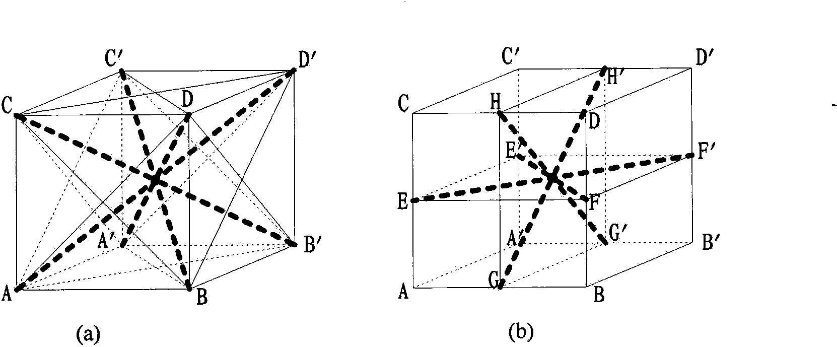
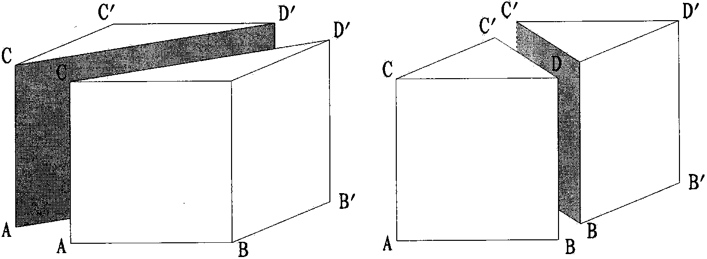
[0064] The concrete acoustic wave penetration mobile unit method for the first phase of the vertical ship lift rack in a hydropower project is tested. The test unit is arranged according to the aforementioned method. See Figure 5 , the thickness between the inner and outer surface of the concrete wall of the first phase of the vertical ship lift rack is 1.5m (the distance between point 1 and point 1'), and the distance between point 1 and point 3 is 1.2m, Penetrating Rays Stereogram Reference image 3 (a), adopt the "gradual movement" method in the longitudinal direction of the concrete wall of the first phase of the vertical ship lift rack, and the moving point distance is 0.1m, and a continuous vertical plane will be formed in the longitudinal direction, that is, the thick black line in the figure is The horizontal projection of the penetrating ray or each thick black line represents a vertical section, such as 1~3', 3~1' vertical secti...

Embodiment 2

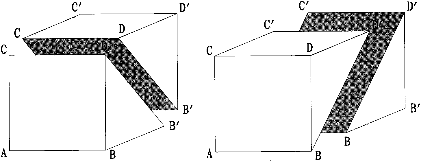
[0072] The concrete acoustic wave penetration mobile unit method for the first phase of the vertical ship lift rack in a hydropower project is tested. The test unit is arranged according to the aforementioned method. See Figure 9 , the thickness between the inner and outer concrete surfaces of the first phase of the vertical ship lift rack is 1.5m (the distance between point 1 and point 1'), and the distance between point 1 and point 3 is 1.2m. The concrete wall of the first stage of the ship lift rack adopts the "gradual movement" method in the vertical direction, with a moving point distance of 0.1m, and the "building block movement" method in the horizontal direction to the right, with a moving step distance of 1.2m, forming a continuous control in the longitudinal direction. Vertical plane, that is, the black thick line in the figure is the horizontal projection of the penetrating ray or each black thick line represents a vertical plane, such as 1~3', 3~1'3~3', 3~5' vertic...


PUM


Abstract

The invention relates to a sound wave penetration detecting method for structures with shapes of larger dimension wall bodies, column bodies, beam bodies and the like, and belongs to the field of engineering earth physical nondestructive detection. According to the invention, initial testing cubic unit is selected on tested structural concrete according to the testing direction, a sound wave emission probe and a sound wave receiving probe are arranged on the relative free face of the cubic unit for carrying out testing, then repeated tests are performed on the cubic unit on the tested structural concrete according to the testing direction through step-by-step moving or building block moving, data processing is performed by using statistics analysis, the characteristics of sound wave kinetics and kinematics as well as image formation technology on sound wave penetration data tested through step-by-step moving or building block moving, and further macroscopical, local and specific screenings are adopted for the data processing results to detect the parts of the structural concrete with quality problems, so that the tested structural concrete can undertake stereoscopic and more comprehensive quality detection with small volume of work.

Description

technical field [0001] The invention relates to a structural concrete sound wave penetration detection method for relatively large-scale walls, columns, beams and other shapes, belonging to the field of engineering geophysics non-destructive testing. Background technique [0002] Structural concrete is one of the main building materials at present. Larger-scale structural concrete buildings, such as dam vertical ship lifts and bridges, are mainly composed of walls, columns, beams and other structural concrete with a thickness of 1.0m to 3.0m. It is composed of dense steel bars, and steel components are often buried in important parts. The construction difficulty of structural concrete, over-shock or under-shock during pouring, and construction reasons will cause defects such as concrete segregation and voids. Finding out the quality defects of structural concrete and dealing with them in a timely manner is the key to eliminating hidden dangers in the project, ensuring projec...

Claims


Application Information

Patent Timeline
Patent Type & Authority Patents(China)
IPC IPC(8): G01N29/04
Inventor 刘润泽张建清詹建生陆二男张智刘方文熊永红余才盛李文忠陈敏曾凡卿李道永闵晓莉况碧波刘新志
Owner CHANGJIANG SURVEY PLANNING DESIGN & RES
Learn More